6 related drive parameters – Yaskawa SI-EN3 Installation User Manual
Page 35
6 Related Drive Parameters
YASKAWA ELECTRIC TOBP C730600 58B 1000-Series Option SI-EN3 Installation Manual
35
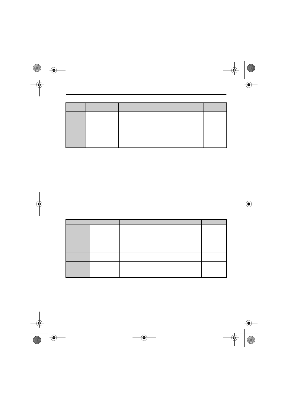
Table 7 Option Monitors
F7-33 to
F7-42
(405 to 40E)
Dynamic Input
Assembly Parameters
Parameters used in Input Assembly 166. Each parameter
contains a MEMOBUS/Modbus address. The value sent for
Input Assembly 166 will be read from this corresponding
MEMOBUS/Modbus address. A MEMOBUS/Modbus
address value of 0 means that the value sent for Input
Assembly 166 is not defined by the user, therefore the option
default register value will be returned.
Refer to Input Assemblies (Drive Produces) on page 39
for
definitions of the default MEMOBUS/Modbus registers.
Default: 0
<1> To start and stop the drive with the EtherNet/IP master device using serial communications, set b1-02 to 3 or set
the “Net Control” bit in the assemblies or Control Supervisor Object. To control the drive frequency reference of
the drive via the master device, set b1-01 to 3 or set the Net Reference bit in the assemblies or AC/DC Object.
<2> If F6-01 is set to 3, the drive will continue to operate when a fault is detected. Take safety measures, such as
installing an emergency stop switch.
<3> A1000: Enabled in CLV, AOLV/PM, and CLV/PM control modes (A1-02 = 3, 6, or 7). When enabled, d5-01
determines whether the value is read as the Torque Limit value (d5-01 = 0) or read as the Torque Reference value
(d5-01 = 1). In CLV/PM, this value is read as the Torque Limit.
Z1000: Enabled in OLV/PM control modes (A1-02 = 5). When enabled, d5-01 determines whether the value is
read as the Torque Limit value (d5-01 = 0) or read as the Torque Reference value (d5-01 = 1). In V/f, this value is
read as the Torque Limit.
<4> The setting specifies that the Torque Reference or Torque Limit is to be provided via network communications
(F6-06 = 1). The motor may rotate if no torque reference or Torque Limit is supplied from the PLC.
<5> Cycle power for setting changes to take effect.
<6> If F7-13 is set to 0, then all IP Addresses (F7-01 to F7-04) must be unique.
<7> Set F7-01 to F7-12 when F7-13 is set to 0.
<8> Set F7-15 when F7-14 is set to 0 or 2.
No.
Name
Description
Value Range
U6-80 to U6-83 Online IP Address
IP Address currently available; U6-80 is the most
significant octet
0 to 255
U6-84 to U6-87 Online Subnet
Subnet currently available; U6-84 is the most significant
octet
0 to 255
U6-88 to U6-91 Online Gateway
Gateway currently available; U6-88 is the most significant
octet
0 to 255
U6-92
Online Speed
Link Speed
10: 10 Mbps
100: 100 Mbps
U6-93
Online Duplex
Duplex Setting
0: Half, 1: Full
U6-98
First Fault
First Option Fault
–
U6-99
Current Fault
Current Option Fault
–
No.
(Addr. Hex)
Name
Description
Values
EtherNet_IM_E_conditional.fm 35 ページ 2012年10月31日 水曜日 午後12時53分