Yaskawa 1000 Series Drive Option - Profibus-DP Technical Manual User Manual
Page 24
7 Option Data and I/O Maps
24
YASKAWA ELECTRIC SIEP C730600 42B 1000-Series Option SI-P3 Technical Manual
If an error occurs, the option sets the Most Significant Bit (MSB) in the MEMOBUS/Modbus response code to 1 and
returns the error response. The number of data items is set to 02H and an error code is written into the Low Byte of Data
Refer to the MEMOBUS/Modbus Communications chapter in the drive Technical Manual for the details on
MEMOBUS/Modbus error codes.
Parameter Settings Using MEMOBUS/Modbus Commands
The written or read data of each parameter is transferred in a hexadecimal value.
Negative values are expressed as a two complement.
Example 1: The frequency reference is 30Hz.
30 Hz/0.01 Hz = 3000
→ BB8H
Example 2:–5% is assigned as the bias for terminal FM of multi-function analog output 1.
5/0.1 = 50
→ 32H
Converted into a two complement
→ FFCEH
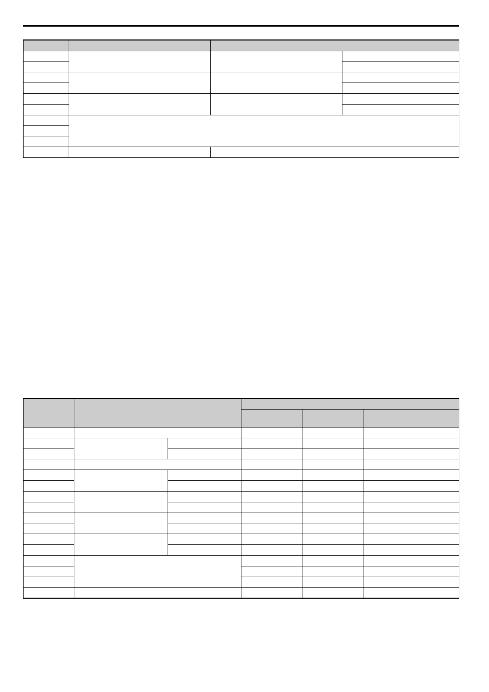
Example 3:60.00 Hz is assigned for d1-01 (register No.: 0280H).
60.00 Hz/0.01 Hz = 6000
→ 1770H
Table 16 Parameter Settings Using MEMOBUS/Modbus Commands
22
Data 2
Data word 2
High Byte
23
Low Byte
24
Data 3
Data word 3
High Byte
25
Low Byte
26
Data 4
Data word 4
High Byte
27
Low Byte
28
Reserved
29
30
31
Handshaking register
Refer to Handshaking Register on page 25
for details.
<1> Data is returned only for the read command.
Byte
<1> Depends on the status of the previous data.
<2> Depends on the status of the fault.
Name
Data
Command
Message
Response
Message
Response Message (at
Fault)
16
Function code
10H
10H
90H
17
Starting Register No.
High Byte
02H
02H
00H
18
Low Byte
80H
80H
00H
19
Number of Data Items
02H
02H
02H
20
Data 1
High Byte
17H
00H
00H
21
Low Byte
70H
00H
02H
22
Data 2
High Byte
00H
00H
00H
23
Low Byte
00H
00H
00H
24
Data 3
High Byte
00H
00H
00H
25
Low Byte
00H
00H
00H
26
Data 4
High Byte
00H
00H
00H
27
Low Byte
00H
00H
00H
28
Reserved
00H
00H
00H
29
00H
00H
00H
30
00H
00H
00H
31
Handshaking Register
80H
80H
80H
Byte
Name
Function