Yaskawa 1000 Series Drive Option - Profibus-DP Technical Manual User Manual
Page 14
5 Installation Procedure
14
YASKAWA ELECTRIC SIEP C730600 42B 1000-Series Option SI-P3 Technical Manual
5.
Select the proper type of 9-pin D-sub CN5 connector and network cable.
for details on cable selections and cable lengths.
Refer to the PROFIBUS-DP website at www.profibus.com for more information on cables and connectors.
6.
Connect the option to the network using a 9 pin D-sub connector as shown in
.
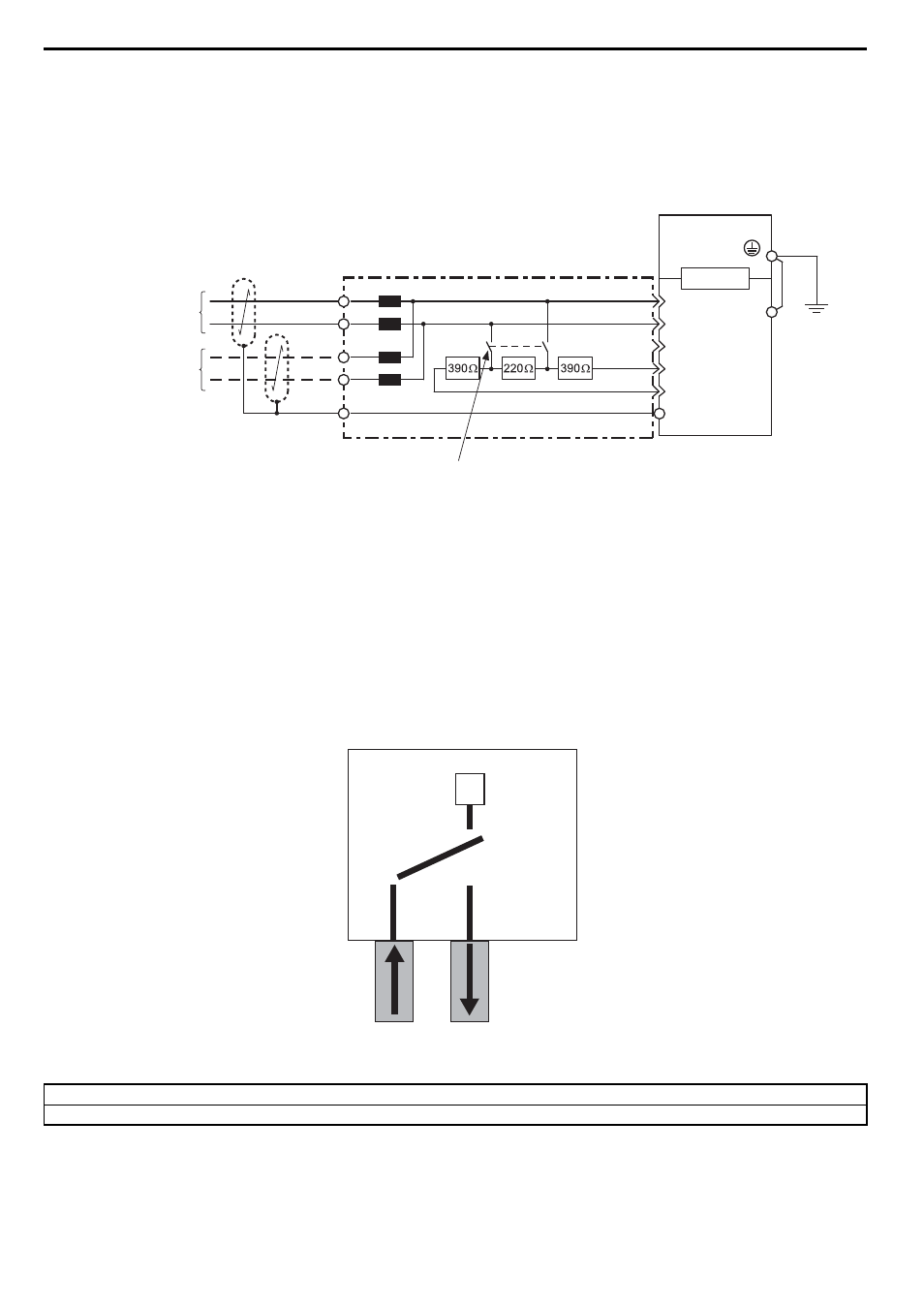
Connection Diagram
Figure 7
Figure 7 Option Connection Diagram
<1> The ground wire provided in the option shipping package must be connected during installation.
PROFIBUS-DP Termination
The option does not have a termination resistor. The termination resistance must be set on the final drive in the
network using a switch on the 9-pin D-sub connector. Make sure that only the connector for the final drive in the
network has a termination resistor; communication problems may arise if any other network drive has a
termination resistor.
Use only the input side cable entry as shown in
when connecting both ends of the network. Most 9-pin
D-sub connectors have a function for disconnecting the output side of the cable. Communication will not be
possible between devices if the connector is reversed. Most connectors have arrows indicating the input and
output sides.
Figure 8
Figure 8 PROFIBUS Cable Connection with Termination Resistors
Bus termination ON = incoming and outgoing cables not connected.
Bus termination OFF = incoming and outgoing cables connected.
Drive
9-pin D-sub Connector
For the last node on the bus,
turn on the termination resistor switch.
SI-P3
RTS
DGND
VP
A-line
B-line
1B
1A
3
8
4
6
5
2B
2A
CN5-A
FE
<1>
PROFIBUS Cable
PROFIBUS Cable Connector
(Red)
(Green)
(Red)
(Green)
(Shell)
To PROFIBUS-DP
Master
To the next slave
(Shell)
ON
OFF
Outgoing Cable
Incoming Cable
Switch
Bus termination
9-pin D-sub Connector
O
O
O