4 mechatrolink-ii option components, Mechatrolink-ii option, Communication connector – Yaskawa 1000 Series Drive Option - MECHATROLINK-II Technical Manual User Manual
Page 9: Mechatrolink-ii option led display, 4mechatrolink-ii option components
4 MECHATROLINK-II Option Components
YASKAWA ELECTRIC
SIEP C730600 50A YASKAWA AC Drive-Option Card MECHATROLINK-II Technical Manual
9
4
MECHATROLINK-II Option Components
MECHATROLINK-II Option
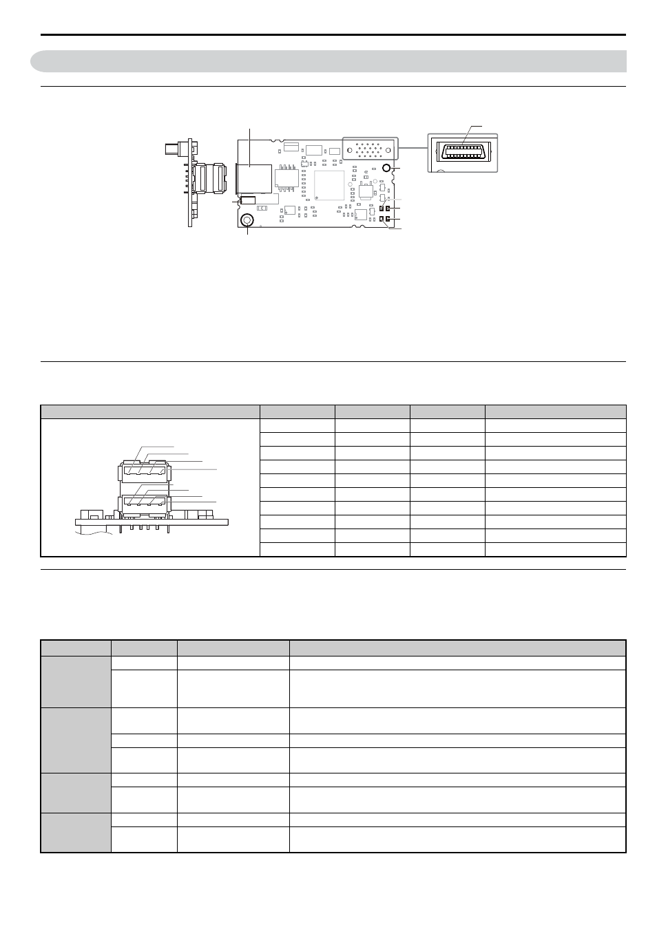
Figure 1
Figure 1 Option Card
For details on the LEDs, Refer to
MECHATROLINK-II Option LED Display on page 9
.
Communication connector
Table 2 Communication connector
MECHATROLINK-II Option LED Display
The MECHATROLINK-II Option has four LEDs that indicate the option card or communication status.
Checking LED Operation
Table 3 MECHATROLINK-II Operation LED Status
A – Communication cable connector
E – LED (ERR)
B – Model number
F – LED (RUN)
C – Ground terminal
(installation hole)
G – LED (TX)
H – LED (RX)
D – Installation hole
I – Connector (CN101)
MECHATROLINK-II Connector
Pin No.
Signal Name
I/O
Function
A1
(NC)
–
Not used.
A2
SRD–
I/O
Send/receive data (–)
A3
SRD+
I/O
Send/receive data (+)
A4
(NC)
–
Not used.
Shell
SLD
–
Shield
B1
(NC)
–
Not used.
B2
SRD–
I/O
Send/receive data (–)
B3
SRD+
I/O
Send/receive data (+)
B4
(NC)
–
Not used.
Shell
SLD
–
Shield
LED
<1> For details on the communication error, refer to
.
Display
Status
Remarks
RUN
ON
Power supply on
SI-T3 has been successfully powered up
OFF
No power
• The drive has no power
• SI-T3 is not properly connected to the drive, or SI-T3 has no power
• An internal, self-diagnostic error occurred in the SI-T3
ERR
ON
Connection error
• SI-T3 is not properly connected to the drive
• Communication error
Flashing
SI-T3 error
Error found during SI-T3's self-diagnostic check
OFF
Normal operation
• SI-T3 is properly connected to the drive
• Communication normal
TX
ON
Sending data
Data is being sent (LED may appear to be flashing)
OFF
Not sending data
• No data is being sent
• During reset
RX
ON
Receiving data
Data is being received (LED may appear to be flashing)
OFF
Not receiving data
• No data is being received
• During reset
Looking from the connector
Underside
SI-T3
A
B
I
D
E
C
H
G
F
A1
A2
A4
A3
B1
B2
B3
B4
CN3