Communications phases, Phase 1: initial status after power on, Phase 2: asynchronous communications – Yaskawa 1000 Series Drive Option - MECHATROLINK-II Technical Manual User Manual
Page 16: 7 transmission interface
7 Transmission Interface
16
YASKAWA ELECTRIC SIEP C730600 50A YASKAWA AC Drive-Option Card MECHATROLINK-II Technical Manual
Figure 6
Figure 7 Basic format of data transfer (32-byte data transmission)
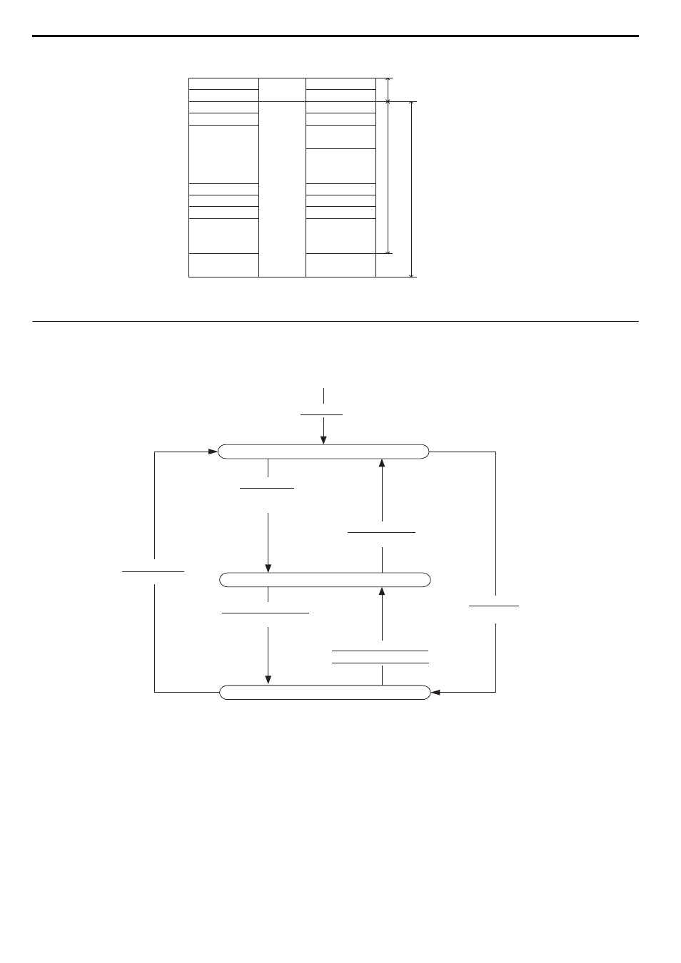
Communications Phases
The SI-T3 changes status as described here when a command code or fault is received from the master.
Figure 7
Figure 8 Communication phases
Phase 1: Initial status after power ON
Operation proceeds with a default transmission cycle of 2 ms. The transmission cycle is changed to the time indicated in
the synchronous frame when a CONNECT command is received from the master. Then the phase moves to phase 2 or
phase 3 after a response to the CONNECT command is returned.
Even if a transfer fault is detected in phase 1, no fault notification is provided.
Phase 2: Asynchronous communications
All SI-T3 commands can be used. Phase 2 starts to count the watchdog timer in the communications frame. The phase
moves to phase 3 when a SYNC_SET command is received, and it moves to phase 1 when a DISCONNECT command is
received.
Command data
Station address
Control code
Command code
−
Data
−
Data
Not used.
Data
Not used.
WDT
Sub-command
Sub-command
Sub-status
Response data
Header of data link layer
Application layer
Data in data link layer
Station address
+00H
+01H
+02H
+03H
+04H
+11H
+12H
+13H
+14H
+1FH
+21H
+00H
+01H
+02H
+03H
+04H
+11H
+12H
+13H
+14H
+1FH
+21H
Control code
Response code
Alarm
Status
Data
EWDT
Power ON
Phase 1 (Initial status)
Phase 2 (Asynchronous communications status)
Phase 3 (Synchronous communications status)
Connecting:
CONNECT command
(Asynchronous communications)
Set Synchronization
(SYNC_SET command)
Communications fault
Watchdog timer fault
Connecting:
CONNECT command
(Synchronous communications)
Disconnecting:
DISCONNECT command
Disconnecting:
DISCONNECT command