7 transmission interface, Mechatrolink-ii cyclic transmissions, Basic format of data transfer – Yaskawa 1000 Series Drive Option - MECHATROLINK-II Technical Manual User Manual
Page 15: 7transmission interface, Are used as application data, Yaskawa electric
7 Transmission Interface
YASKAWA ELECTRIC
SIEP C730600 50A YASKAWA AC Drive-Option Card MECHATROLINK-II Technical Manual
15
7
Transmission Interface
MECHATROLINK-II Cyclic Transmissions
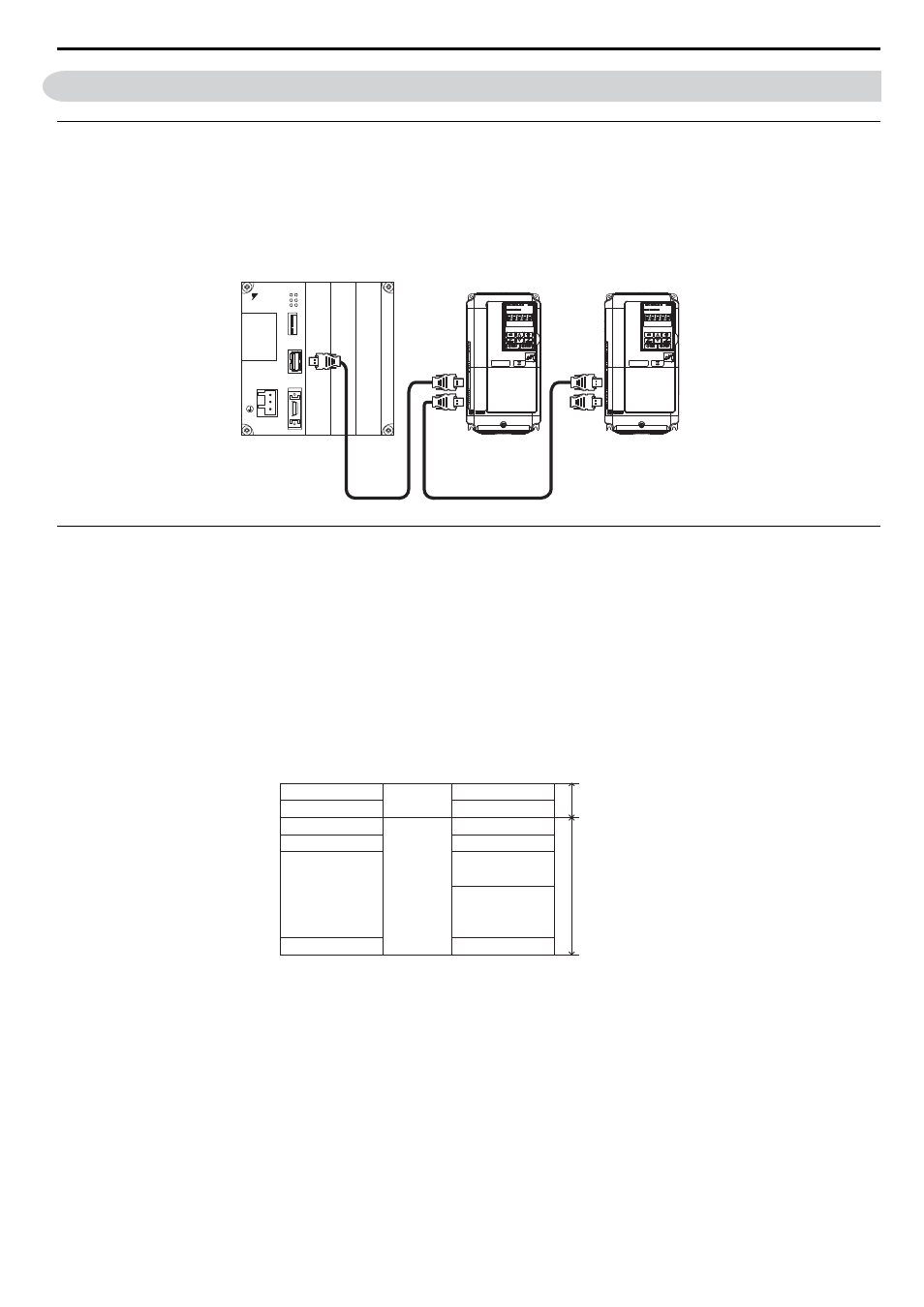
As a MECHATROLINK-I/MECHATROLINK-II station, the SI-T3 exchanges control data and I/O data with a control
device, such as a controller. Communications with the master are executed by sending response data timed to the
reception of command data for the local station address from the master in each transmission cycle. The formats for the
command and response data follow the specifications for the MECHATROLINK Drive commands.
Basic Format of Data Transfer
The basic format for transferring data is as follows.
The size of the header for a data link layer is fixed at two bytes.
By setting, either 17 bytes (17-byte data transmission) or 32 bytes (32-byte data transmission) can be selected as the data
size for the data link layer. If 32-byte data transmission is selected, only the first 29 bytes
are used as application
data.
Figure 5
Figure 6 Basic format of data transfer (17-byte data transmission)
<1> The first 30 bytes are used only when the INV_I/O sub-command is used.
Terminator
Master: MP2300 Controller (Example)
MP2300
YASKAWA
TEST
ޓ
ޓ
ޓ
RDY
ALM
TX
RUN
ERR
BAT
MON
CNFG
INT
SUP
STOP
SW1
OFF
ON
BATTERY
CPU I/O
DC24V
DC 0V
M-
I/II
Command data
Station address
Control code
Command code
−
Data
WDT
Response data
Header of
data link layer
Data link layer data
and application layer
Station address
+00H
+01H
+02H
+03H
+04H
+06H
+11H
+12H
+00H
+01H
+02H
+03H
+04H
+11H
+12H
Control code
Response code
Alarm
Status
Data
EWDT