Application layer specifications, Phase 3: synchronous communications – Yaskawa 1000 Series Drive Option - MECHATROLINK-II Technical Manual User Manual
Page 17
7 Transmission Interface
YASKAWA ELECTRIC
SIEP C730600 50A YASKAWA AC Drive-Option Card MECHATROLINK-II Technical Manual
17
Phase 3: Synchronous communications
Watchdog timer faults in the communications frame are detected. If the DISCONNECT command is received, the phase
moves to phase 1. If a reception fault or a watchdog timer fault is detected, the phase moves to phase 2.
Application Layer Specifications
The data format for the application layer conforms to the MECHATROLINK-II link command specifications.
SI-T3 has the following main commands and sub-commands.
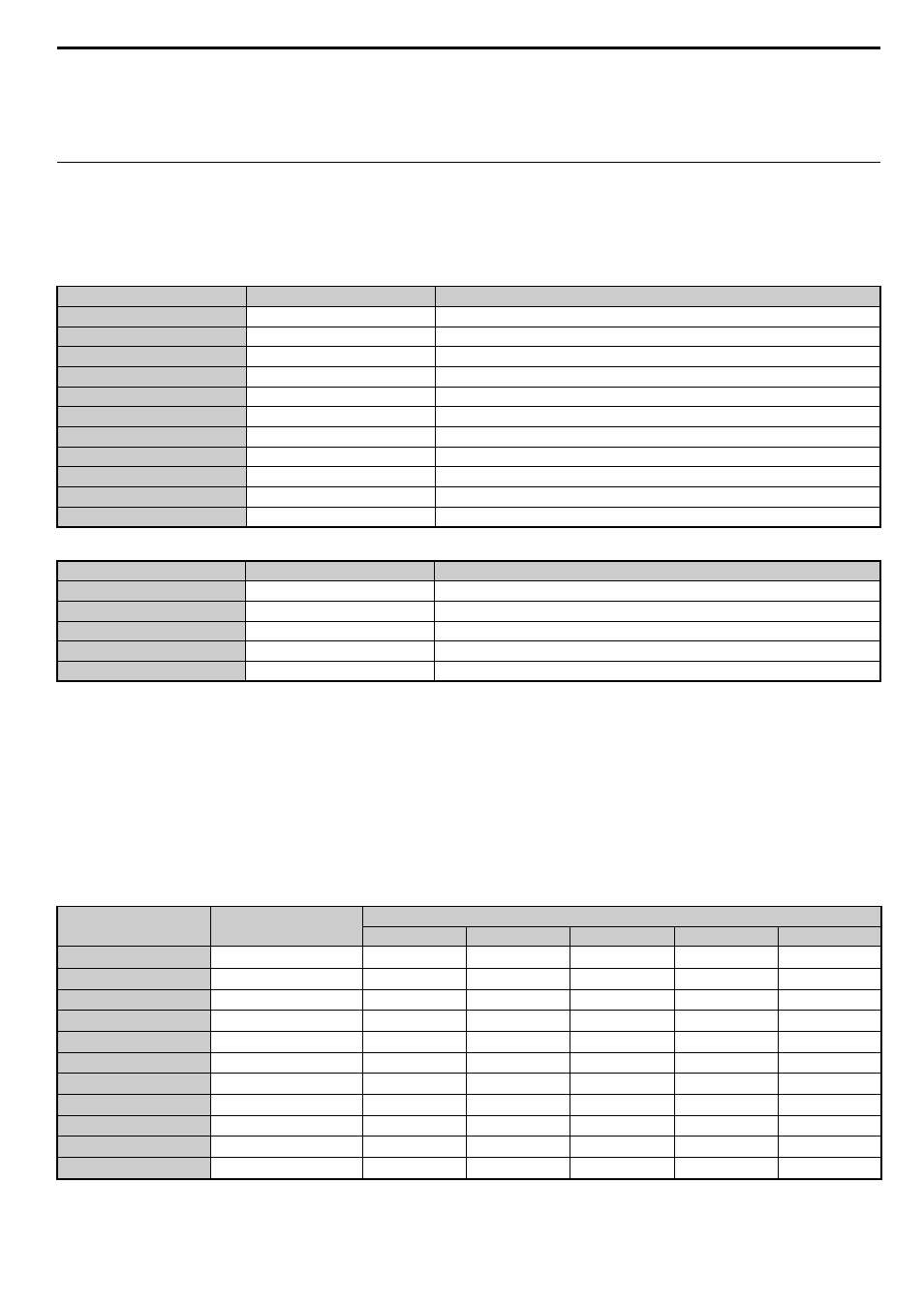
Table 5 Main Commands
Table 6 Sub-commands
The main commands are used in both the 17-byte and 32-byte data transmissions for MECHATROLINK-II and with
MECHATROLINK-I. The sub-commands can be used only when the 32-byte data transmission (F6-21 = 0) has been
selected. If a conflict occurs between a request for a main command and a request for a sub-command, the request for the
main command is processed. If either a main command or a sub-command is already being processed, the command
being processed is given priority. If an INV_CTL main command and an INV_I/O sub-command conflict, the sub-
command is given priority.
For details on command formats, refer to
MECHATROLINK-II Commands on page 18
.
The following table shows the combination of Main Commands and Sub-commands.
Table 7 Main Command and Sub-command
Note: Command warning (A.95) will result if a main command and sub-command conflict with one another. For details on the alarm,
Code
Name
Function
00H
NOP
No Operation
01H
PRM_RD
Read Parameter
02H
PRM_WR
Write Parameter
03H
ID_RD
Read ID Number
04H
CONFIG
RAM Write and EEPROM Write
05H
ALM_RD
Read Alarm and Warning
06H
ALM_CLR
Clear Alarm and Warning
0DH
SYNC_SET
Start Synchronous Communications
0EH
CONNECT
Connect
0FH
DISCONNECT
Disconnect
40H
INV_CTL
Drive Operation Control
Code
Name
Function
00H
NOP
No Operation
01H
PRM_RD
Read Parameter
02H
PRM_WR
Write Parameter
05H
ALM_RD
Read Alarm and Warning
41H
INV_I/O
Drive I/O Control
Code
Main Command
Sub-command
NOP (00H)
PRM_RD (01H) PRM_WR (02H) ALM_RD (05H) INV_I/O (41H)
00H
NOP
OK
OK
OK
OK
OK
01H
PRM_RD
OK
NG (A.95)
NG (A.95)
OK
OK
02H
PRM_WR
OK
NG (A.95)
NG (A.95)
OK
OK
03H
ID_RD
OK
OK
OK
OK
OK
04H
CONFIG
OK
NG (A.95)
NG (A.95)
NG (A.95)
NG (A.95)
05H
ALM_RD
OK
NG (A.95)
NG (A.95)
NG (A.95)
NG (A.95)
06H
ALM_CLR
OK
NG (A.95)
NG (A.95)
NG (A.95)
NG (A.95)
0DH
SYNC_SET
OK
OK
OK
OK
OK
0EH
CONNECT
OK
NG (A.95)
NG (A.95)
NG (A.95)
NG (A.95)
0FH
DISCONNECT
OK
NG (A.95)
NG (A.95)
NG (A.95)
NG (A.95)
40H
INV_CTL
OK
OK
OK
OK
OK