SMA WB 5000A-11 Installation User Manual
Page 43
SMA Solar Technology AG
Electrical Connection
Installation Manual
WB5A_6A-IA-IEN114540
43
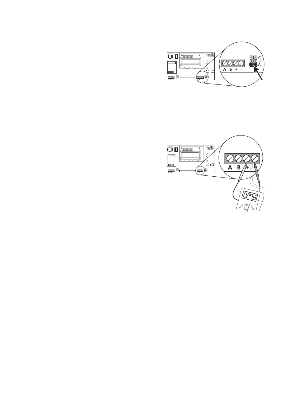
8. Only in the middle inverter
(the one with 2 insulated conductors per terminal),
insert one of the jumpers provided into the lowest of
the three slots as depicted on the right.
Do not plug the jumpers into the bottom slot of the
two other inverters.
or
Bridge the "A" and "B" screw terminals on the
middle inverter with a wire bridge.
Do not bridge the "A" and "B" screw terminals in
the two other inverters!
9. Measure the resistance between the positive and
negative poles of the terminal block in the middle
inverter.
☑ If the resistance is approximately 27.8 k Ω
(±370 Ω ), the SMA Power Balancer has been
connected correctly. Otherwise, check the
cabling.
10. Close all inverters as described in Section