SMA SC 200 Installation User Manual
Page 67
SMA Solar Technology AG
External Connections
Installation Guide
SC20_25_35-IEN094521
67
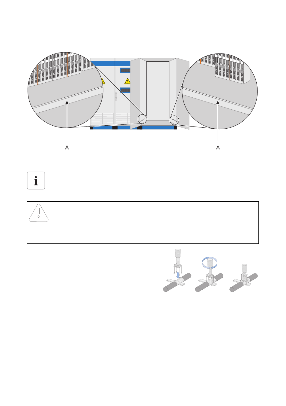
The following diagram shows the position of the connection terminals in the Sunny Central 350.
1. Remove the line insulation.
2. Attach the shield clamp.
☑ The shield clamp snaps into place.
3. Tighten the shield clamps hand-tight. Tightening
using a screwdriver is not necessary.
A
Connection point for shielded contact rail
Position of the connection terminals for signal and bus lines.
The exact position of the connection terminals for signal and bus lines can be determined
with the help of the equipment identifier and the circuit diagram enclosed.
NOTICE!
Damage to the shield clamps.
• Only tighten the shield clamps hand-tight.
• Tightening the shield clamps using a screwdriver can damage the insulation.