3 inserting the cables – SMA GRID CONNECT BOX 12 User Manual
Page 25
SMA Solar Technology AG
9 Periodic Actions
Operating Manual
GRID-BOX-12-3-20-BE-en-10
25
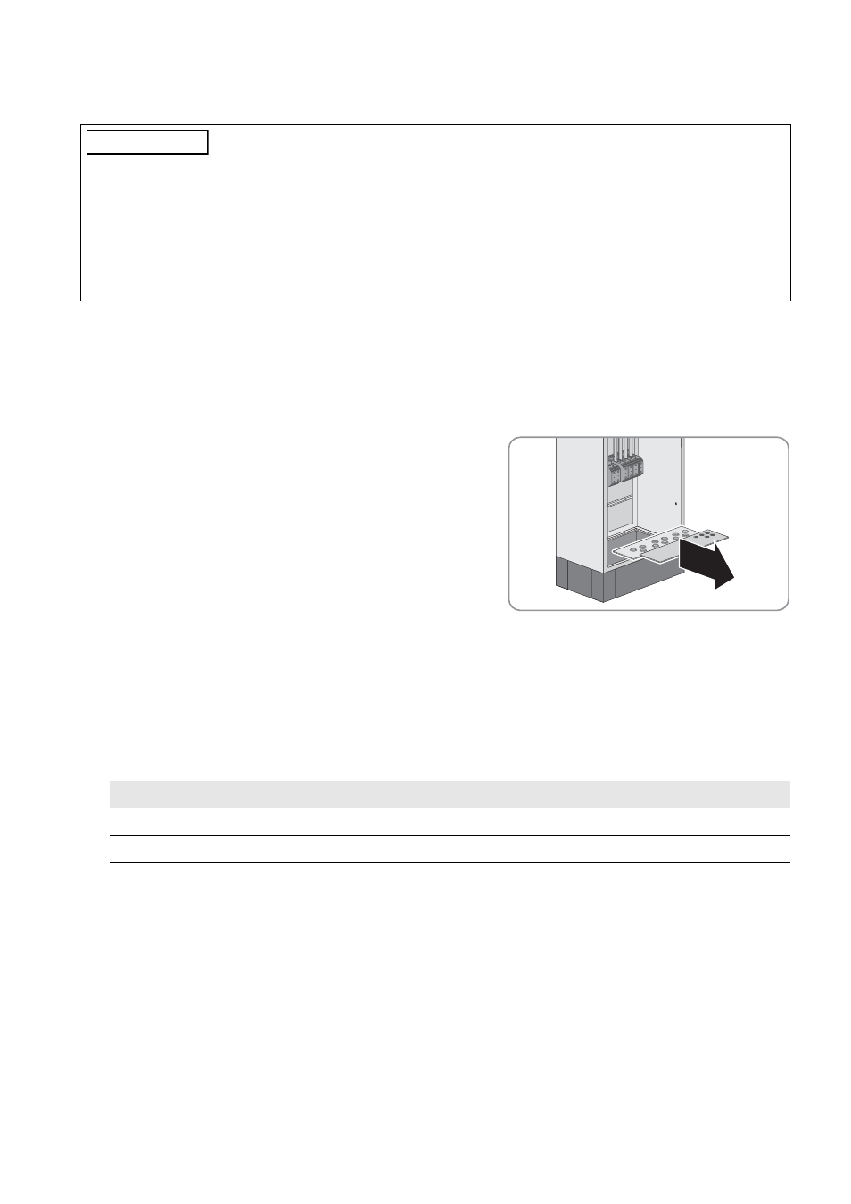
9.3 Inserting the Cables
Requirement:
☐ The kick plates must be dismantled (see Section 5.4.2 "Transporting and Mounting the Grid Connect Box",
Procedure:
1. Disassemble the protective cover of the Grid Connect Box (see Section 9.1, page 23).
2. Remove all screws of the front and rear base plates on the floor of
the Grid Connect Box (TX 25) and remove the base plates.
3. Insert each cable into the Grid Connect Box as follows:
• Select a suitable enclosure opening for the given cable.
• Pierce the membrane of the selected enclosure opening with a pointed object. Make sure that you do not make
the opening too large.
• Insert each cable through the membrane of the selected enclosure opening into the Grid Connect Box. Ensure
that the cable is tightly enclosed by the membrane.
• Strip the insulation of each cable .
4. Insert the base plate and tighten all screws (TX 25 screwdriver, torque: 9 Nm).
5. Attach the kick plates to the Grid Connect Box with the fastening screws (TX 30, torque: 12 Nm).
/05*$&
Damage to the Grid Connect Box due to moisture penetration
Dust and moisture can penetrate the Grid Connect Box due to overstretched or damaged membranes. Moisture and
dust intrusion can cause irreparable damage to the Grid Connect Box.
• When selecting the enclosure opening, match the diameter of the membrane to the diameter of the cable.
• Choose a suitable tool for piercing the membrane
• Ensure that the membrane is not ruptured when the cable is inserted.
Cable type
Stripping length
Power cable
40 mm
Control cable
20 mm