4 connecting the utility grid, 5 connecting the control cables – SMA GRID CONNECT BOX 12 User Manual
Page 19
SMA Solar Technology AG
6 Electrical Connection
Operating Manual
GRID-BOX-12-3-20-BE-en-10
19
6.4 Connecting the Utility Grid
Cable requirements:
☐ Conductor material: copper
☐ The conductor cross-section must be selected according to the rated input power of the utility grid.
☐ Conductor cross-section: 50 mm² to 150 mm²
☐ The power cables must be ground-fault and short-circuit protected.
☐ Line conductors, the neutral conductor and grounding conductor must have the same cross-section.
Procedure:
1. Insert the power cables of the Multicluster Box into the Grid Connect Box (see Section 9.3, page 25).
2. Connect the grounding conductor to the spring-cage terminal PE at terminal X301:4 (see Section 9.4.1, page 26).
3. Connect the neutral conductor to the spring-cage terminal N at terminal X301:5.
4. Connect the line conductors to the spring-cage terminals L1, L2 and L3 at terminal X301:1-3.
5. Ensure that a right-hand rotating magnetic field is present at the grid-connection point.
6. Provide for strain relief of the power cables in the spring-cage terminal by attaching them to the appropriate cable
support rail. Use the cable clamps and counter-sleeves provided.
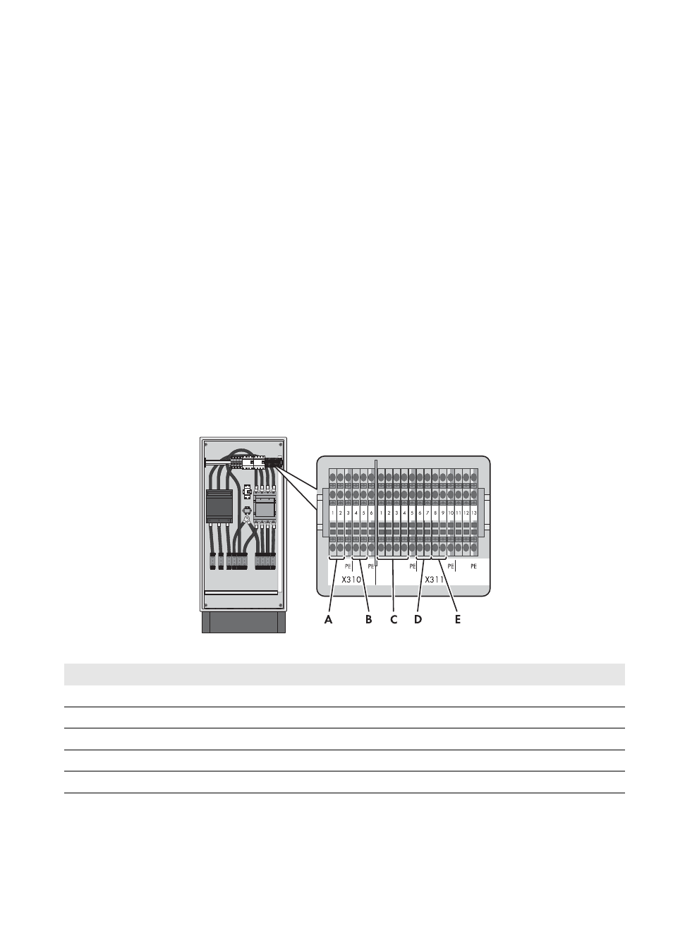
6.5 Connecting the Control Cables
Assignment of spring-cage terminals with the control cables:
Figure 10: Overview of spring-cage terminals in the Grid Connect Box
Position
Explanation
A
Block of grounding contactor of Multicluster Box
B
Feedback from grid contactor of Grid Connect Box
C
Voltage measurement of Grid Connect Box
D
Block of generator contactor of Multicluster Box
E
Block of grid contactor of Grid Connect Box