6 electrical connection, 1 overview of the connection area, 1 components and terminals – SMA GRID CONNECT BOX 12 User Manual
Page 17
SMA Solar Technology AG
6 Electrical Connection
Operating Manual
GRID-BOX-12-3-20-BE-en-10
17
6 Electrical Connection
6.1 Overview of the Connection Area
6.1.1 Components and Terminals
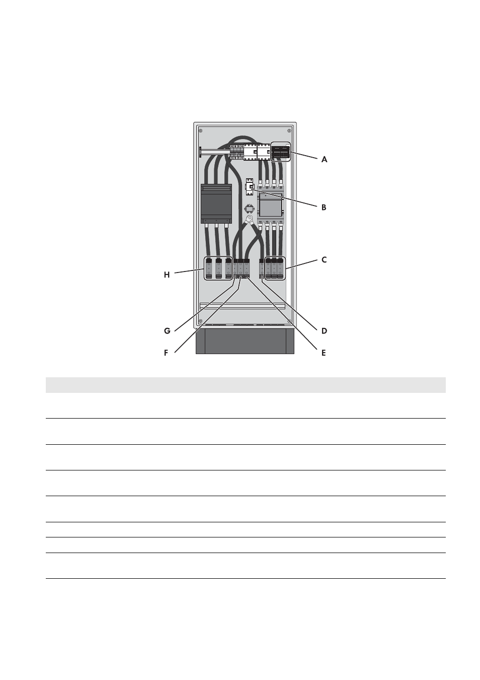
Figure 8: Overview of the Connection Area
Item
Designation
Explanation
A
Terminal X310, X311 with spring-cage
terminals
Spring-cage terminals for connecting the control cables
B
Surge arrester
The signal light on the surge arrester must be checked
regularly (see Section 10.2, page 29).
C
Terminal X301:8-10 with spring-cage
terminals L1, L2 and L3
For connecting the line conductors of the Multicluster Box
D
Terminal X301:7 with spring-cage terminal PE For connecting the grounding conductor of the
Multicluster Box
E
Terminal X301:6 with spring-cage terminal N For connecting the neutral conductor of the Multicluster
Box
F
Terminal X301:5 with spring-cage terminal N For connecting the neutral conductor of the utility grid
G
Terminal X301:4 with spring-cage terminal PE For connecting the grounding conductor of the utility grid
H
Terminal X301:1-3 with spring-cage terminals
L1, L2 and L3
For connecting the line conductors of the utility grid