2 enclosure openings in the floor, 2 deactivating all-pole disconnection, 3 connecting the multicluster box – SMA GRID CONNECT BOX 12 User Manual
Page 18
6 Electrical Connection
SMA Solar Technology AG
18
GRID-BOX-12-3-20-BE-en-10
Operating Manual
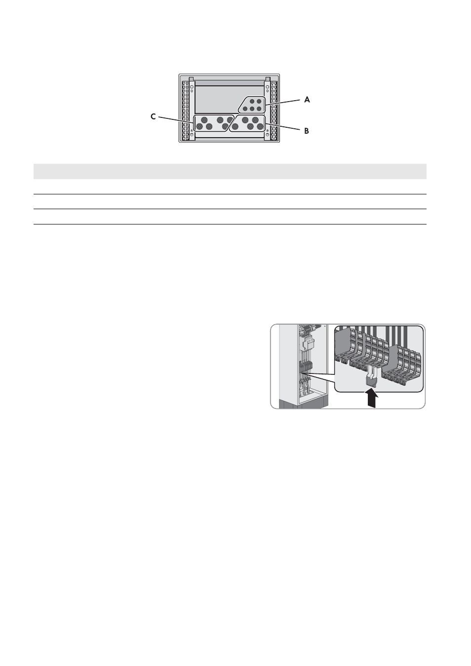
6.1.2 Enclosure Openings in the Floor
Figure 9: Position of the enclosure openings
6.2 Deactivating All-Pole Disconnection
The technical connection requirements of the grid operator and the local standards and directives specify if the
multicluster system, in the event of grid failure, disconnects from the utility grid at all poles or only the line conductors.
The Grid Connect Box is always delivered with all-pole disconnection. If all-pole disconnection is not permitted, you must
deactivate the all-pole disconnection function on the Grid Connect Box. To do this, insert the supplied two-pole N bridge
as follows:
Procedure:
• For use of the Grid Connect Box without all-pole disconnection,
connect spring-cage terminal N to X301:5 and spring-cage
terminal N to X301:6. Insert the supplied N bridge into the
spring-cage terminals from below.
6.3 Connecting the Multicluster Box
Cable requirements:
☐ Conductor material: copper
☐ Conductor cross-section: 50 mm² to 150 mm²
☐ The power cables must be ground-fault and short-circuit protected.
☐ Line conductors, the neutral conductor and grounding conductor must have the same cross-section.
Procedure:
1. Insert the power cables of the Multicluster Box into the Grid Connect Box (see Section 9.3, page 25).
2. Connect the grounding conductor to the spring-cage terminal PE at terminal X301:7 (see Section 9.4.1, page 26).
3. Connect the neutral conductor to the spring-cage terminal N at terminal X301:6.
4. Connect the line conductors to the spring-cage terminals L1, L2 and L3 at terminals X301:8-10.
5. Ensure that a right-hand rotating magnetic field is present at the connection point of the Multicluster Box.
6. Provide for strain relief of the power cables in the spring-cage terminal by attaching them to the appropriate cable
support rail. Use the cable clamps and counter-sleeves provided.
Position
Explanation
A
Enclosure openings for the control cables
B
Enclosure openings for the power cables of the Multicluster Box
C
Enclosure openings for the power cables of the utility grid