Operation, User interface – Grass Valley Thunder 80 v.1.0 User Manual
Page 45
29
Thunder
User Guide
Operation
User Interface
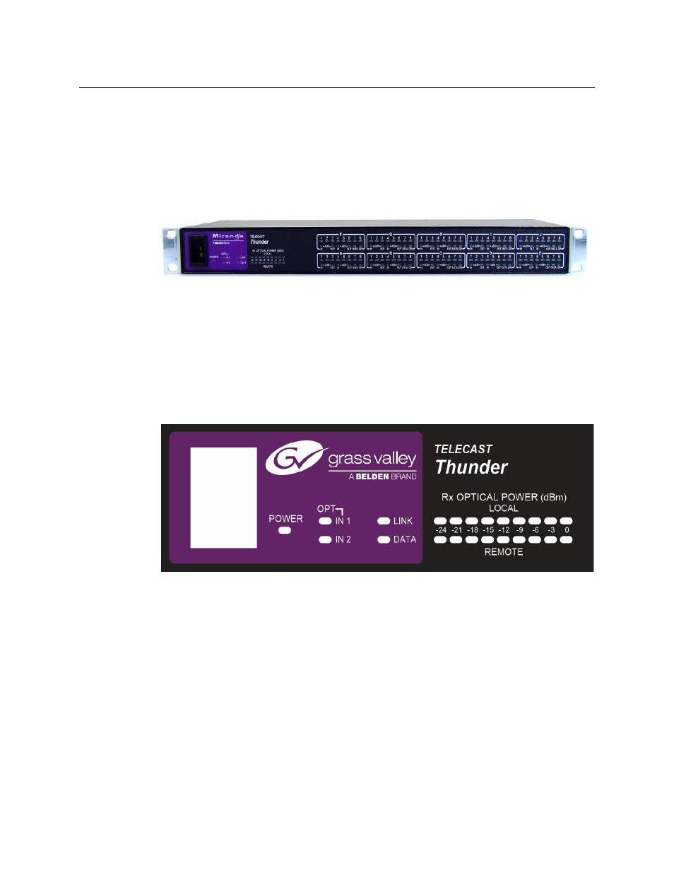
The Thunder front panel incorporates a series of LEDs that are used to display the system
status to the user.
Primary Display
The primary display on the left side
has LED indicators for: Power, Optical input 1 and 2
status conditions (channel in use/un-used channel “readiness”), System Link, Data
Activity (for data channels 1 and 2 on the mainboard only), and 2 “Local” / “Remote” bar
graphs with 9 segments, 3dBm/segment, each representing optical input power applied to
both the local and remote Thunder chassis’.
Power
Indicates the input power conditions of the Thunder chassis:
• Unlit when the power switch is turned off.
• Illuminates solid yellow (red/green mix) when powered on and the primary power (AC
Line Input) source only is being supplied to the chassis.
• Illuminates solid green when powered on and both the primary (AC Line) and
secondary (10Vdc to 30Vdc) power sources are being supplied to the chassis.
• Illuminates solid red when powered on, but the primary power has failed and the
chassis is now operating on the secondary (back-up) power source.
OPT - IN 1
Indicates status/conditions of the primary SFP optical receiver.