Connection details – Grass Valley Thunder 80 v.1.0 User Manual
Page 38
22
System Implementation
• Some audio breakout panels provide inputs/outputs for two banks of 8 channels. These
carry one connector for each 8-channel bank, and are associated with one ThunderBolt
card for each bank.
• The Data/GPI breakout PANEL may support either one or two Data Bolt cards in
addition to the GPI Bolt card.
Fiber inputs and outputs connecting the two ends of the system together are located on
the frame’s rear panel.
• The entire bidirectional data package is carried on dual fibers.
• A second fiber plate carrying the same data package is available so that a back-up,
redundant signal path can be established to protect the integrity of the program.
• WDM SFP cartridges are available, allowing bidirectional communication over a single
fiber.
Connection Details
All connections to the Thunder frame are located on the rear panel.
The 10 connectors on the left-hand side of the rear panel are associated with the Bolt cards
installed in the frame.
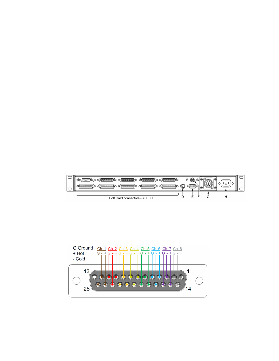
A - Analog Audio Bolt Card Connectors
Analog audio Boltcards connect to their associated breakout panels via a ribbon cable
equipped with DB25 connectors. These use standard “Tascam” pinouts for analog audio, as
shown in the following figure.
Fig. 3-1: Tascam DB25 pinouts for analog audio
The connector pinout is shown in the figure and the table.