Installing/removing intercom modules, Breakout panel – Grass Valley Thunder 80 v.1.0 User Manual
Page 34
18
Thunder System Components
Installing/Removing Intercom Modules
The interface is compatible with powered or unpowered belt packs, as well as fixed
equipment. You may power up to five belt packs with each intercom module. Refer to your
intercom manufacturer’s documentation for additional system details.
For operation with a belt pack, adjust the following:
• set the PORTS to w (powered)
• the TERM to ON
• center each of the INPUT gain, OUTPUT gain, and NULL controls
Readjust these controls to optimize performance as required.
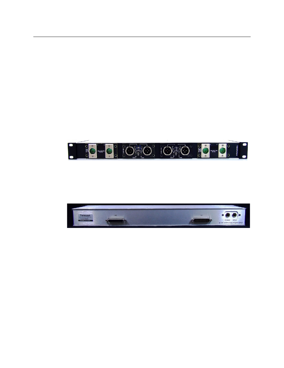
Breakout Panel
The Intercom breakout panel has four bays for installing intercom modules.
Within the panel, the various intercom signals are arranged and packaged into an input
group and an output group. These are presented on the rear panel on two DB25
connectors. The inputs (Rx) are connected to an Audio IN Bolt card, while the outputs (Tx)
are connected to an Audio OUT bolt card.
In addition to the audio I/O connectors, the rear panel has two 30 VDC intercom power
inputs - a primary input, and a secondary redundant input.
Installing/Removing Intercom Modules
Before attemping any module exchange, the Intercom breakout panel should be powered
OFF .
Two multi-conductor cable harnesses are built into the Intercome breakout panel and run
behind the module locations. These cables connect the intercom modules to power and
signal sources. There are AMP-MTA type connectors for each module on this harness; the
connector fits all module types.
• Signal is 8-pin
• Power is 2-pin