System implementation, 3 system implementation, Installation – Grass Valley Thunder 80 v.1.0 User Manual
Page 37
21
System Implementation
This chapter describes the installation, setup and configuration of the Thunder 80-channel
audio/data/intercom link.
Installation . . . . . . . . . . . . . . . . . . . . . . . . . . . . . . . . . . . . . . . . . . . . . . . . . . . . . . . . . . . . . . . . . . . . . . . . . . . 21
Connection Details . . . . . . . . . . . . . . . . . . . . . . . . . . . . . . . . . . . . . . . . . . . . . . . . . . . . . . . . . . . . . . . . . . . 22
Operation . . . . . . . . . . . . . . . . . . . . . . . . . . . . . . . . . . . . . . . . . . . . . . . . . . . . . . . . . . . . . . . . . . . . . . . . . . . . 29
Installation
Each end of a Thunder audio/data/intercom link requires an identical equipment package.
This comprises a rack containing:
• A Thunder frame (1 RU), with installed ThunderBolt cards
• Either:
• Breakout panels as required for the installed ThunderBolt cards
• Cables connecting the frame to the breakout panels.
• Or:
• Snake cables (DB25 to 8 XLR)
• Power source as available at the site
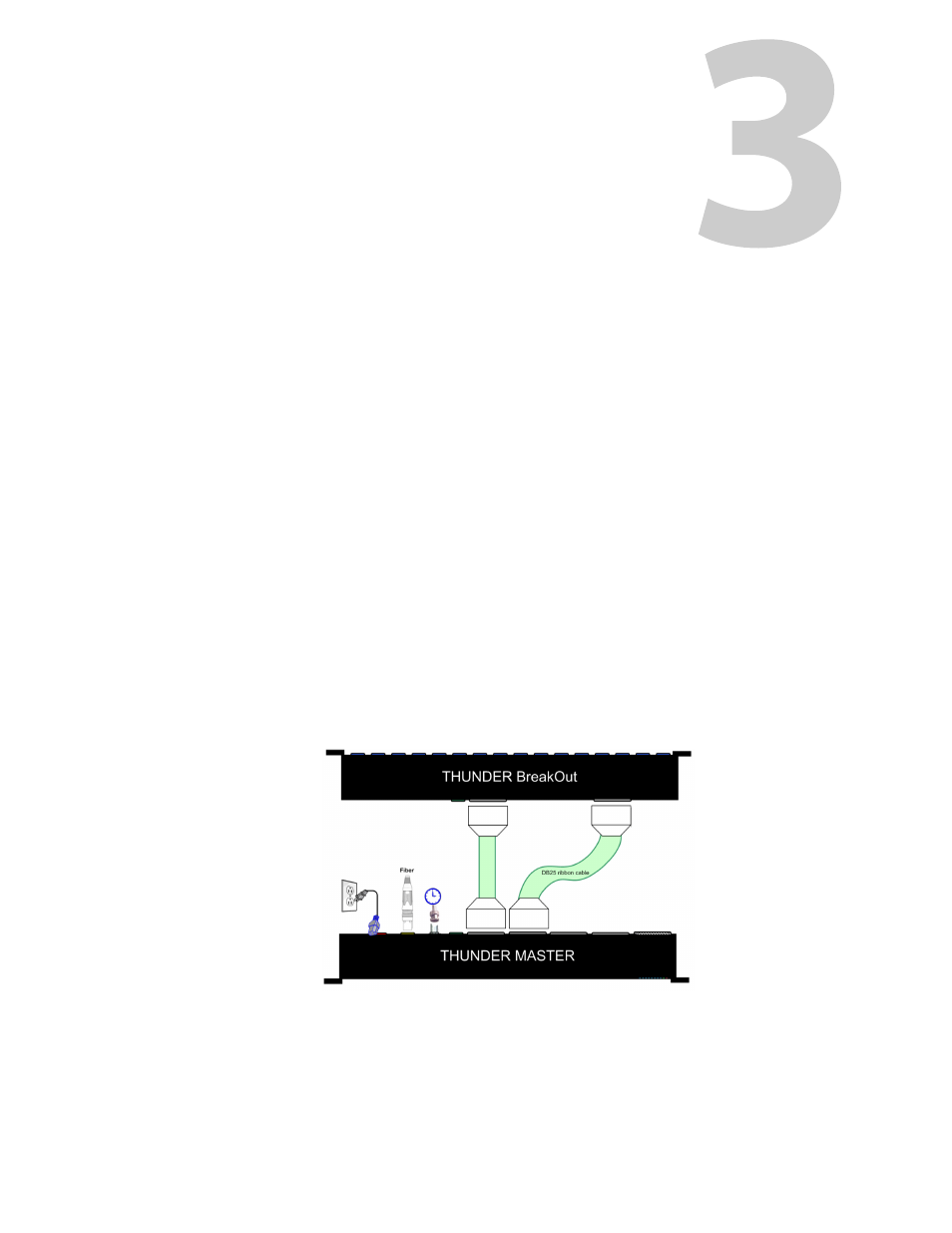
Interconnections within the rack are made using multiconductor ribbon cables.
• Each ThunderBolt card within the Frame is associated with a connector on the frame’s
rear panel. Each card and its associated connector handle signals for eight channels.
• Each breakout panel has a connector that carries 8 channels of data.