Set up system hardware and connect video, Pvs 3000 default video connections – Grass Valley PVS 3000 July 2004 User Manual
Page 7
23 February 2004
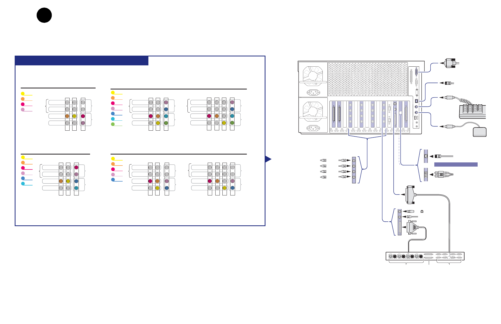
Set up system hardware and connect video
7
Profile XP Media Platform
PVS 3000 Default Video Connections
Reference In
LTC & GPI
RS-422
75 Terminator
Fibre Channel
Video network
I/O Panel
LTC In/Out
RS-422
GPI In/Out
Push
Push
Push
Push
SVGA
Monitor
Ethernet
Video network
AND / OR
Play (HD Out)
Record (HD In)
Monitor (SD SDI)
Monitor (NTSC/PAL)
HD SDI
Mouse
Keyboard
Ethernet
Windows NT
Network
In B
In A
Out A
Out B
SDI 2In/2Out
PVS 3004
Channel names
Video Connections
Vtr1
Vtr2
Vtr3
Vtr4
NTSC/PAL
SD SDI
Monitor
Record
Play
HD-SDI
SDI
2In/2Out
A
B
A
B
Recor
d
Pla
y
PVS 3014
Channel names
Video Connections
NTSC/PAL
SD SDI
Monitor
Record
Play
HD-SDI
Video Connections
with Embedded Audio
SDI
2In/2Out
A
B
A
B
Recor
d
Pla
y
SDI
2In/2Out
A
B
A
B
Recor
d
Pla
y
Vtr1
Vtr2
Vtr3
Vtr4
Vtr5
NTSC/PAL
SD SDI
Monitor
Record
Play
HD-SDI
PVS 3024
Channel names
Video Connections
Vtr1
Vtr2
Vtr3
Vtr4
Vtr5
Vtr6
NTSC/PAL
SD SDI
Monitor
Record
Play
HD-SDI
SDI
2In/2Out
A
B
A
B
Recor
d
Pla
y
PVS 3534
Channel names
Video Connections
Video Connections
with Embedded Audio
Vtr1
Vtr2
Vtr3
Vtr4
Vtr5
Vtr6
Vtr7
NTSC/PAL
SD SDI
Monitor
Record
Play
HD-SDI
SDI
2In/2Out
A
B
A
B
Recor
d
Pla
y
HD-SDI
NTSC/PAL
SD SDI
Monitor
Record
Play
SDI
2In/2Out
A
B
A
B
Recor
d
Pla
y
Notes
:
Video I/Os are assigned beginning with Vtr1 and the HD-SDI board in the lowest numbered board slot. SD clips are upconverted on HD outputs.
SD I/Os are assigned after HD I/Os. SD outputs play down-converted HD clips.
NTSC/PAL and SD SDI connections are for monitoring purposes only.
1
Set up system hardware and connect video
Using the diagrams on this or the following page, set up the system hardware as shown, then
locate your PVS 3000 Series model (PVS 3000 or PVS 3500) under Default Video
Connections. Use the color coding to make the video I/O connections for the recorder and
player channels.