Grass Valley PVS 3000 July 2004 User Manual
Page 15
23 February 2004
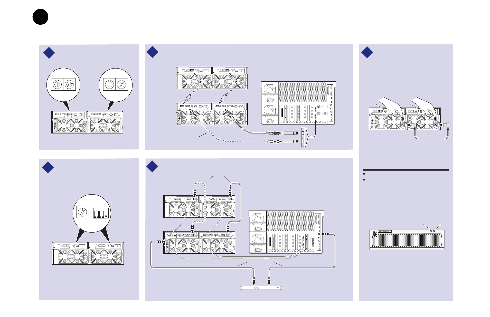
Set up the RAID Storage: PFR700/E (Local storage only)
15
Connect Fibre Channel cabling as shown.
3
1
PFR 700
RAID
Chassis
PFR 700E*
Expansion
Chassis
Maximum of 1 Expansion Chassis
Media Platform
Port A
* If Installed
This cable and SFP used for PFR 700
with optional RAID Controller 1.
Port B
2
Set Fibre Channel addresses on both
PFR 700 controllers.
Set the same Chassis Address and
diagnostic ID on both PFR 700E
Expansion Adapters, if installed.
0
2
Address ID = 2*
*If Installed
0
1
Address ID = 1
1
Chassis
Address = 1
ID = "0"
4 3
2 1 ON
Install Ethernet and diagnostic cabling as shown.
4
PFR 700
RAID Chassis
PFR 700E*
Expansion
Chassis
Media Platform
Ethernet Hub or Switch
* If Installed
Ethernet cables
Diagnostic cables*
Power Cords
(115V/230V)
5
Power-up Verification
Ready LEDs on RAID controllers are steady ON.
Front panel Power LED is ON, Service LED is OFF
after approximately 3 minutes.
Refer to the PFR 700 Instruction Manual if there is a
problem.
Power LED
Ready
LED
Ready
LED
Connect power cords, and turn on
power as shown. You must power-up
the PFR
700E Expansion chassis prior
to, or at the same time as the PFR
700
RAID Controller chassis. Verify power-
up as shown.
POWER
SERVICE
PFR
700
!
Service LED
Optical SFPs
IMPORTANT: If you are installing your PVS3000 as part of an Open SAN, do not
perform this RAID storage setup. Instead, follow the instructions in the
Open SAN
Instruction Manual
for setting up RAID storage.
3
a
3
e
Set up the RAID Storage: PFR700/E
(Local storage only)
Use this diagram to set up the PFR 700/E Fibre Channel addresses and to connect
Fibre Channel, Ethernet, and diagnostic cabling.