Grass Valley PVS 3000 July 2004 User Manual
Page 11
23 February 2004
Set up the RAID Storage: PFR500/E (Local storage only)
11
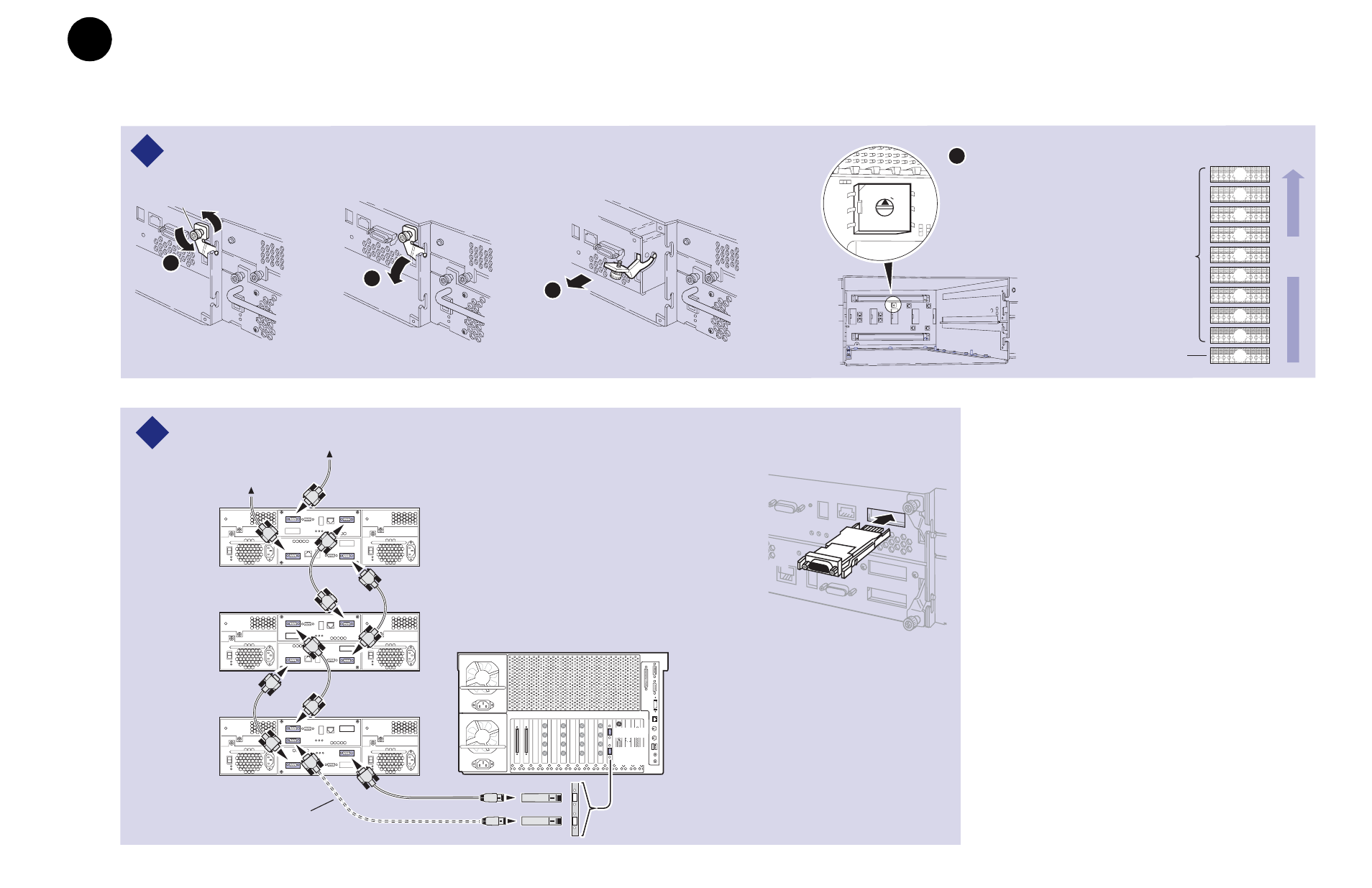
Install all SFPs and GBICs provided so that you can connect Fibre Channel cabling as shown.
Set chassis addresses on all PFR 500E Expansion Chassis.
2
1
PFR 500
RAID
Chassis
PFR 500E*
Expansion
Chassis
PFR 500E*
Expansion
Chassis
Maximum of 9 Expansion Chassis
C
Media Platform
Port A
* If Installed
This cable, SFP, and GBIC used for
PFR 500s with optional RAID Controller B.
Chassis Addresses
PFR 500 RAID
Controller Chassis
(factory set to "0")
PFR 500E RAID
Expansion Chassis
(if installed)
9
8
7
6
5
4
3
2
1
0
Order of
daisy
chain
A
B
Loosen
retaining screws
Remove both Loop Bypass
Board modules to access the
chassis address switch on the
midplane board. Set the switch
to the appropriate address as
shown in the Chassis Address
diagram.
0 1
2
3
45
6
7
8
9
D
Port B
Installing a GBIC
(Gigabit Interface Converter)
Copper SFPs
IMPORTANT: If you are installing your PVS3000 as part of an Open SAN, do not
perform this RAID storage setup. Instead, follow the instructions in the
Open SAN
Instruction Manual
for setting up RAID storage.
3
b
33
a
3
a
Set up the RAID Storage: PFR500/E
(Local storage only)
Use this diagram to set up the PFR 500/E chassis addresses and to connect Fibre
Channel cabling, then proceed to step 3b on the next page.