Set up raid storage: pfc500/e (local storage only), Open san instruction manual, Power-up verification – Grass Valley PVS 3000 July 2004 User Manual
Page 10: For setting up raid storage
10
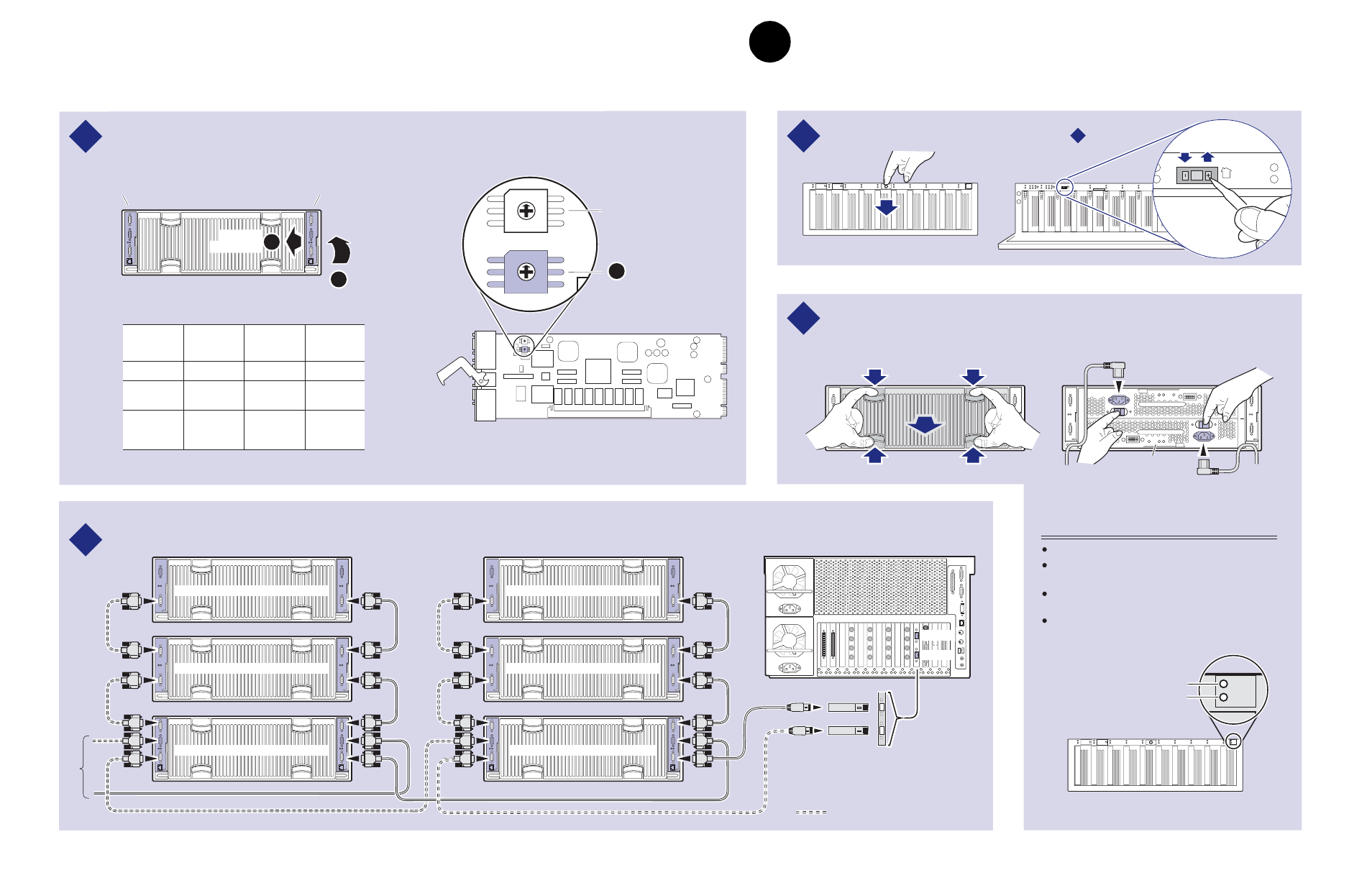
Set up RAID Storage: PFC 500/E (Local storage only)
23 February 2004
Connect Fibre Channel cabling.
Set the Fibre Channel Loop Address ID on each RAID Controller as shown.
2
1
Power Cord
(115V/230V)
Power Cord (115V/230V)
Optional
Power Supply
Connect power cords and turn on power as shown.
Begin with PFC
500E(s), if installed. Verify proper power-up as shown.
0
1
2
3
4
5
6
7
8
9
#
0
2
4
1
3
5
#
6
8
1 0
7
9
1 1
0
1
2
3
4
5
6
7
8
9
#
0
2
4
1
3
5
#
#
6
8
1 0
7
9
1 1
#
0
2
3
Set Chassis
Addresses
1
Lower the
front door
Set required chassis addresses, refer to Step .
A
P/S
B
ON
l
OFF
0
ON
l
OFF
0
3
4
PFC 500 Chassis Address = 0
PFC 500E* Chassis Address = 1
PFC 500E* Chassis Address = 2
* If Installed
PFC 500* Chassis Address = 0
PFC 500E* Chassis Address = 1
PFC 500E* Chassis Address = 2
Pull out
controller
PFC 500 Rear Panel
A
B
Lift handle
Optional Redundant
RAID Controller
Primary
RAID Controller
RAID Controller Board
C
0
7
6
5
4
3
2
1
0
E
C
A
8
6
4
2
F
D
B
9
7
5
3
1
0
7
6
5
4
3
2
1
0
E
C
A
8
6
4
2
F
D
B
9
7
5
3
1
Top Switch
(always set to "0")
Set Fibre Channel
Loop Address ID
settings. Refer to
the table.
Maximum of 5 PFC
500 Chassis
0626-13
Media Platform
Port A
Port B
0
1
2
3
4
5
6
7
8
9
#
0
2
4
1
3
5
#
6
8
1 0
7
9
1 1
System Check LED
Power LED
Power-up Verification
Power LED is on.
System Check LED turns off after approximately 90
seconds.
The PFC500 requires approximately 2 to 3 minutes
to fully initialize. All disk access LEDs are on.
Refer to the
PFC 500 Instruction Manual if there is
a problem.
2
Number of
PFC
500s *
* For systems with greater than three PFC500s, use the
same numbering pattern as shown.
PFC 500
Chassis
Primary
Controller
Address ID
Redundant
Controller
Address ID
1
2
3
First
First
Second
First
Second
Third
0
0
1
0
1
2
1
2
3
3
4
5
Fibre Channel Loop Addresses
Redundant system cabling
Copper SFPs
IMPORTANT: If you are installing your PVS3000 Series (PVS3000 or PVS3000 Series)as part of an
Open SAN, do not perform this RAID storage setup. Instead, follow the instructions in the
Open SAN
Instruction Manual
for setting up RAID storage.
3
Set up RAID Storage: PFC500/E
(Local storage only)
Use this diagram to set up the PFC 500 Fibre Channel RAID Chassis and the PFC 500E
Expansion Chassis (if used).