Output, Gpio configuration concepts – Grass Valley NV9605 v.1.1 User Manual
Page 56
46
GPIO
GPIO Configuration Concepts
During contact closure, a current of 1.2mA flows. A maximum of 48VDC can be applied to the
tally input for less than 5 seconds without failure. No voltage above 5VDC should be continu-
ously applied.
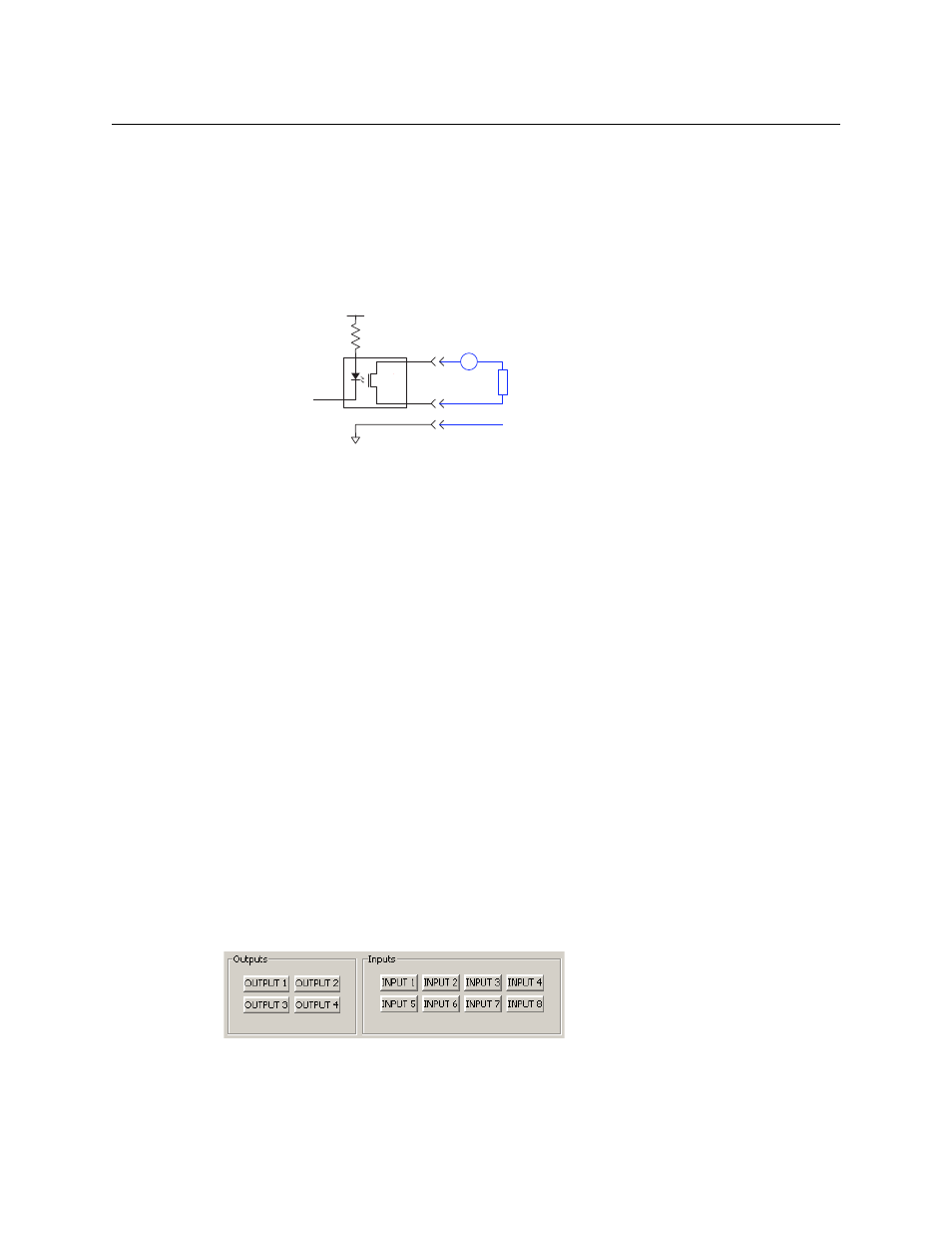
Output
A tally output is a solid state relay (no audible click) with a maximum resistance of 10W and
current capability of 150mA. It can tolerate 200VAC.
Fig. 6-3: GPI Output
When a condition (defined for the relay) occurs, the router control system notifies the NV9605
which then opens or closes the relay. The relay switches the customer’s circuit on or off. (It does
not power the circuit. Customers must provide their own power.)
GPIO Configuration Concepts
These are the I/O characteristics of the NV9605’s tally interface:
•
Eight optically isolated inputs (sometimes called GPIs) that can be configured to trigger an
event when the input transitions from off to on and to trigger another event on a transition
from on to off. Events include:
•
Execute a salvo.
•
Route the “previous source” switched by any panel to a destination.
•
Route the “previous source” switched by this panel to a destination.
•
Route a source to a destination.
•
Four relays that can be configured to switch on a number of conditions:
•
One or more routes occurring on specific levels.
•
Conditions involving output ports (destination, level).
•
A transition on one or more of the panel’s tally inputs.
The GPIO Section of the NV9605 Page
SE’s NV9605 configuration page provides a GPIO section, below the tree window:
Click on a button under ‘Outputs’ to configure one of the 4 tally outputs.
Click on a button under ‘Inputs’ to configure one of the 8 tally inputs.
There are no actual GPIO buttons on the NV9605 control panel.
Optical
Isolation
Customers Load
+5V
499
+
from internal bus
Tally Output n
V
Optional Grounding