Grass Valley Kayenne Installation Planning Guide Aug 30 2011 User Manual
Page 64
64
KAYENNE — Installation Planning Guide
Section 4 — System Cabling
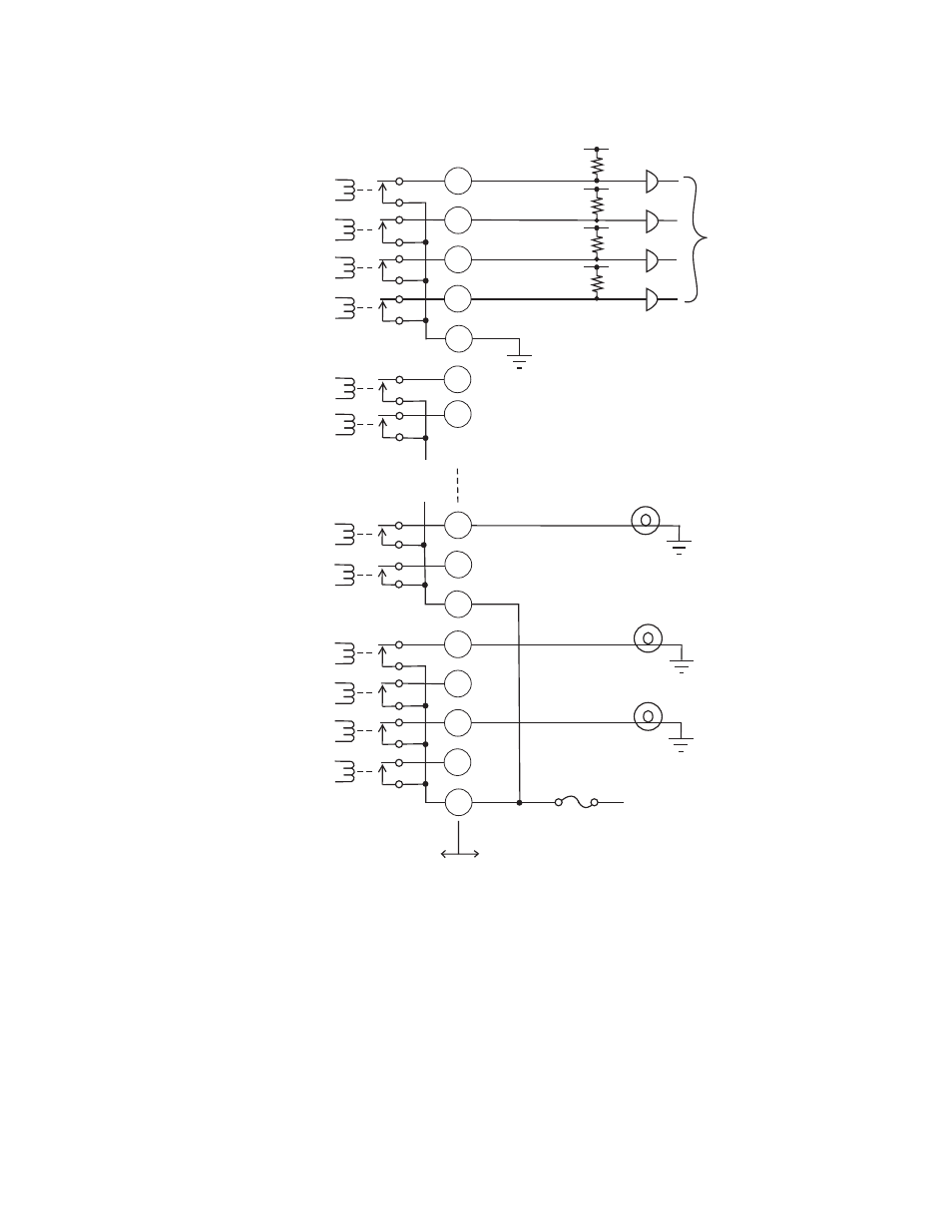
Figure 60. Tally and GPI Output Connection Example
The example shown in
illustrates two common busses. The first
four outputs (COMMON A) have the common bus tied to ground. This
drives a logic system. The last outputs (COMMON G and COMMON H)
have the common bus tied to +12 volts. This drives a tally lamp system.
Although diagram shows mechanical relays, the actual outputs are imple-
mented with solid state relays. The solid state relays are bidirectional;
either polarity voltage can be applied. If the switcher GPI/Tally outputs are
used to drive downstream DC relays, be sure to install diodes across the
50-pin Connector
Pin Numbers
1A of 32
2A of 32
3A of 32
4A of 32
5B of 32
6B of 32
27G of 32
28G of 32
29H of 32
30H of 32
31H of 32
32H of 32
Kayenne Video
Processor Frame
User Equipment
Common B
Common A
Common H
Logic
12V Lamp
12V Lamp
12V Lamp
+ 12V DC
Common G
8623266_46
21
5
38
22
37
39
23
48
32
47
49
33
17
50
16
- LDK 5302 (24 pages)
- SFP Optical Converters (18 pages)
- 2000GEN (22 pages)
- 2011RDA (28 pages)
- 2010RDA-16 (28 pages)
- 2000NET v3.2.2 (72 pages)
- 2000NET v3.1 (68 pages)
- 2020DAC D-To-A (30 pages)
- 2000NET v4.0.0 (92 pages)
- 2020ADC A-To-D (32 pages)
- 2030RDA (36 pages)
- 2031RDA-SM (38 pages)
- 2041EDA (20 pages)
- 2040RDA (24 pages)
- 2041RDA (24 pages)
- 2042EDA (26 pages)
- 2090MDC (30 pages)
- 2040RDA-FR (52 pages)
- LDK 4021 (22 pages)
- 3DX-3901 (38 pages)
- LDK 4420 (82 pages)
- LDK 5307 (40 pages)
- Maestro Master Control Installation v.1.5.1 (455 pages)
- Maestro Master Control Installation v.1.5.1 (428 pages)
- 7600REF Installation (16 pages)
- 7600REF (84 pages)
- 8900FSS (18 pages)
- 8900GEN-SM (50 pages)
- 8900NET v.4.3.0 (108 pages)
- Safety Summary (17 pages)
- 8900NET v.4.0.0 (94 pages)
- 8906 (34 pages)
- 8911 (16 pages)
- 8900NET v.3.2.2 (78 pages)
- 8914 (18 pages)
- 8912RDA-D (20 pages)
- 8916 (26 pages)
- 8910ADA-SR (58 pages)
- 8920ADC v.2.0 (28 pages)
- 8920ADC v.2.0.1A (40 pages)
- 8920DAC (28 pages)
- 8920DMX (30 pages)
- 8920ADT (36 pages)
- 8920MUX (50 pages)
- 8921ADT (58 pages)