Processor frame connectors, Rocessor, Rame – Grass Valley KayakDD-1 Installation User Manual
Page 45: Onnectors, Figure 14, Video processor frame connectors, 5 processor frame connectors, Kayakdd-1 digital production switcher, J 41 j 42, J 44 j 43
KayakDD-1 Digital Production Switcher
6.5
Processor Frame Connectors
N4067
GPI/O - Tally
LAN
RS 485
INPUT
REFERENCE
AUX
M/E
This device complies with part 15 of the FCC Rules. Operation is subject to the following two conditions:
(1) This device may not cause harmful interference, and
(2) this device must accept any interference received, including interference that may cause undesired operation.
AC POWER IN
100 - 240 V
max. 4A
50/60 Hz
DC POWER
IN
OUT
J2
J3
J 4
J 5
J 6
J 7
J 8
PGM-A
CLEAN
PVW-A
CLEAN-PVW
AUX 1
AUX 2
AUX 3
AUX 4
AUX 5
AUX 6
AUX 7
AUX 8
AUX 9
AUX 10
J 9
J 10
J 11
J 12
J 13
J 14
J 15
J 16
J 17
J 18
Port 1
Port 2
Port 3
Port 4
Port 5
Port 6
J 19
J 20
J 21
J 22
J 24
J 23
J 25
IN 1
IN 2
IN 3
J 26
J 27
J 28
J 29
J 30
J 31
J 32
J 33
J 34
J 35
J 36
J 37
J 38
J 39
J 40
IN 4
IN 5
IN 6
IN 7
IN 8
IN 9
IN 10
IN 11
IN 12
IN 13
IN 14
IN 15
IN 16
J 41
J 42
ANALOG
J 44
J 43
grass valley
48V / 5A max.
KAYAK
DD
1 M/E DIGITAL SWITCHER
48V / 1,6A
R
3S13
Prof. Vid. Equipm.
Listed
Caution:
For continued protection against risk
of fire, repplace only with same type and rating of fuse.
2*T6,3A /H
250V
J1
+
-
+
-
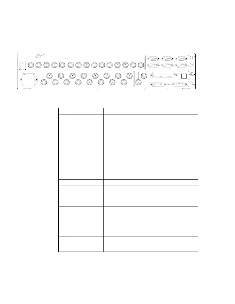
Figure 14
Video Processor Frame Connectors
Jack Designation
Note
J1
AC POWER IN
Mains connector (IEC-320, CEE-22) for power supply
to the Video Processor Frame.
Operating Voltage: 100V-240V AC +/-10% auto-range
Caution!
Double-pole or neutral fusing.
After operation of the protective device, parts of
the equipment that remain under voltage might
represent a hazard during servicing.
Caution!
For continued protection against risk of fire,
replace only with same type and rating of fuse!
2x 6.25A /T 250
AC POWER IN
Frame power switch
J25
:
J40
INPUTS
IN1 – IN16
BNC / Serial Comp (ITU-R 656) video inputs
J4/J5
J6
J7
J8
M/E OUTPUTS
PGM-A
PVW-A
PGM-B
PVW-B
BNC / Serial Comp (ITU-R 656)
Double Program output, A channel
Preview output, A channel
Program output, B channel
Preview output, B channel
J9
:
J18
AUX 1 – AUX10
Auxiliary Outputs, BNC / Serial Comp (ITU-R 656)
44
Planning and Installation Manual