Basic connections, Cables and adapters, Projector + av equipment – Epson LVP-X200A User Manual
Page 12: English, Projector + dvd player
12
ENGLISH
Cables and adapters
To connect personal computers to this projector, the following cables and adapters are necessary. The overview
might be different from the picture below.
RGB cables (mini D-SUB 15P plug)
.
Note:
The pins numbered 5, 9, 12 and 15 are not connected.
RGB Conversion adapter for MAC
(mini D-SUB 15P plug - D-SUB 15P plug)
Basic connections
This projector can be connected to equipment such as VCRs, video cameras, videodisc players, and personal comput-
ers having analog RGB input.
Important:
• Make sure that your equipment is turned off before connection.
• Match the color of video and audio plugs on the AV cable with each terminal.
• Plug in firmly and unplug by holding the plug, not by pulling the cable out.
• If connected units are set too close to one another, the image may be affected. Setting connected units too close
to one another affects the image.
• Refer to the owner's guide of each component for details of connections, .
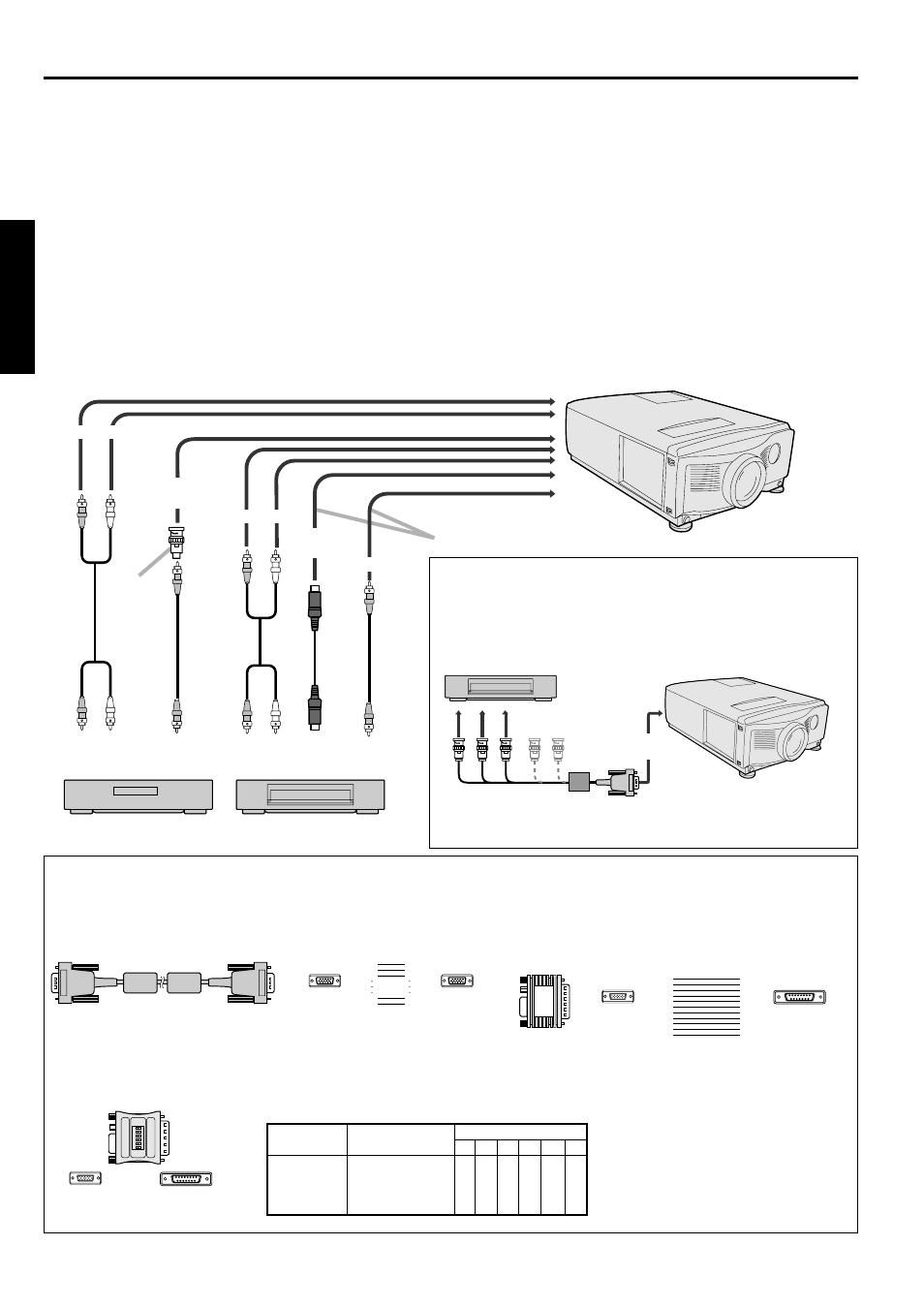
Projector + AV equipment
Make sure that your equipment is turned off before connection.
Important:
S-video signals take priority over video signals. If you input both S-video signals and normal video signals at the
same time, the normal video input automatically shuts off.
to audio
output
to video
output
to S-video
output
to audio
output
to video
output
Connect either one of these.
DVD player, others
to audio input 2
to S-video
input 2
to video input 2
to audio input 1
to video
input 1
VCR, others
RCA/BNC
adaptor
Projector + DVD player
Some DVD players have output terminal for 3 line fitting (Y, C
B
,
C
R
). When connecting them to the projector, connect to RGB-1 or
RGB-2 of the projector. In this case, set “Y, C
B
, C
R
” for RGB/Y, C
B
,
C
R
setting in SIGNAL SETTING MENU.
to RGB 1 IN
or RGB 2 IN
G
R B
C
B
Y
C
R
HD/CS
VD
DVD player
No connection
• Use mini D-SUB 15 pin-BNC conversion cable for connection.
• Some DVD player may not project the image correctly.
PIN NO.
1
2
3
13
14
15
PIN NO.
1
2
3
13
14
15
MINI D-SUB 15P
MINI D-SUB 15P
MINI D-SUB 15P
D-SUB15P
1
2
3
4
5
6
ON
DIP
Note: Set the dip switch to the appropriate position.
%
Display
Resolution
Dip switch
mode
1
2
3
4
5
6
13 inch
640
×
480
ON ON OFF OFF OFF OFF
16 inch
832
×
624
OFF ON OFF ON OFF OFF
19 inch
1024
×
768
OFF ON ON OFF OFF OFF
21 inch
1152
×
870
ON ON ON ON OFF OFF
PIN NO.
1
3
5
8
2
4
6
12
14
15
SHELL
PIN NO.
1
2
3
5
6
7
8
10
13
14
SHELL
MINI D-SUB 15P
D-SUB15P
RGB Conversion adapter for NEC PC (Option)
(mini D-SUB 15P plug - D-SUB 15P plug)