About setting up the commlink tr6442i, Example commlink tr6442i, Fiber optic intercom link usage scenarios – Grass Valley TR6442i User Manual
Page 26: Example
22
Setting Up the CommLink TR6442i
About Setting up the CommLink TR6442i
About Setting up the CommLink TR6442i
Use of the CommLink TR6442i Fiber Optic Intercom Link system first requires the setup and
connection of the Intercom System and the CommLink TR6442i Fiber Optic Intercom Link
Link units. The second step is the proper configuration or setting of switches on the
CommLink TR6442i Fiber Optic Intercom Link front panel. If two-wire systems are in use, the
Auto Null function should be employed.
Each system setup is based on the appropriate mix of the three physical types of the
CommLink TR6442i Fiber Optic Intercom Link. Depending on your particular operation the
combination of units may be all the same physical type or a mix and match. Whatever the
physical configuration of the units, they must operate in pairs of 1310mm WDM and
1550mm WDM units. It makes no difference where the WDM units are placed in the system.
If the CommLink TR6442i Fiber Optic Intercom Link is being used locally to convert
between intercom system types, either WDM type can be used
Example CommLink TR6442i Fiber Optic Intercom Link Usage Scenarios
Five usage configurations are illustrated:
• Connecting a Two Channel Base System with Remote Belt Packs
• Connecting a Matrix Frame System with Two Remote Matrix Stations
• Connecting a Matrix Frame with Remote Belt Packs
• Connecting Two Matrix Stations System with a Matrix Frame with Video Multiplexed on
to a Multi-Strand Fiber Cable (This is an example of "hybrid" use with the CommLink
TR6442i Fiber Optic Intercom Link)
• Converting a Two Channel System to work with a Matrix Frame
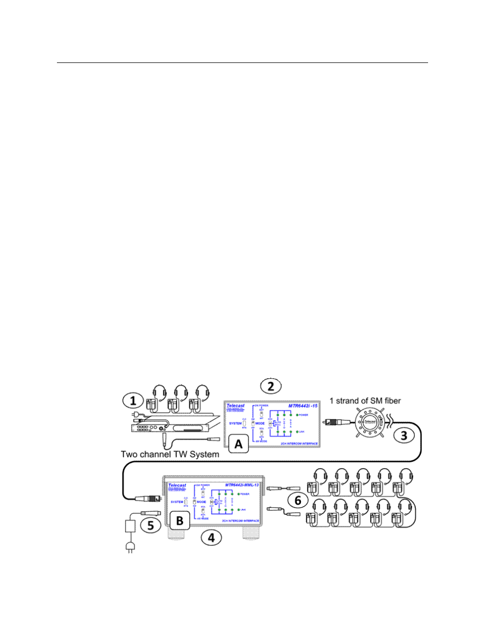
Connecting a Two Channel Base System with Remote Belt Packs
Fig. 3-1: Connecting a Two Channel Base System with Remote Belt Packs