Area a - system configuration switches, Area b - auto null operation – Grass Valley TR6442i User Manual
Page 14
10
System Overview
CommLink TR6442i Fiber Optic Intercom Link Fiber Optic Intercom Link Front Panel
Area A - System Configuration Switches
The four switches in this section allow the configuration of the CommLink TR6442i Fiber
Optic Intercom Link for the particular intercom environment in use. See
CommLink TR6442i Fiber Optic Intercom Link Usage Scenarios
on page 22 below on
operation of the CommLink TR6442i Fiber Optic Intercom Link for examples of how these
switches interact.
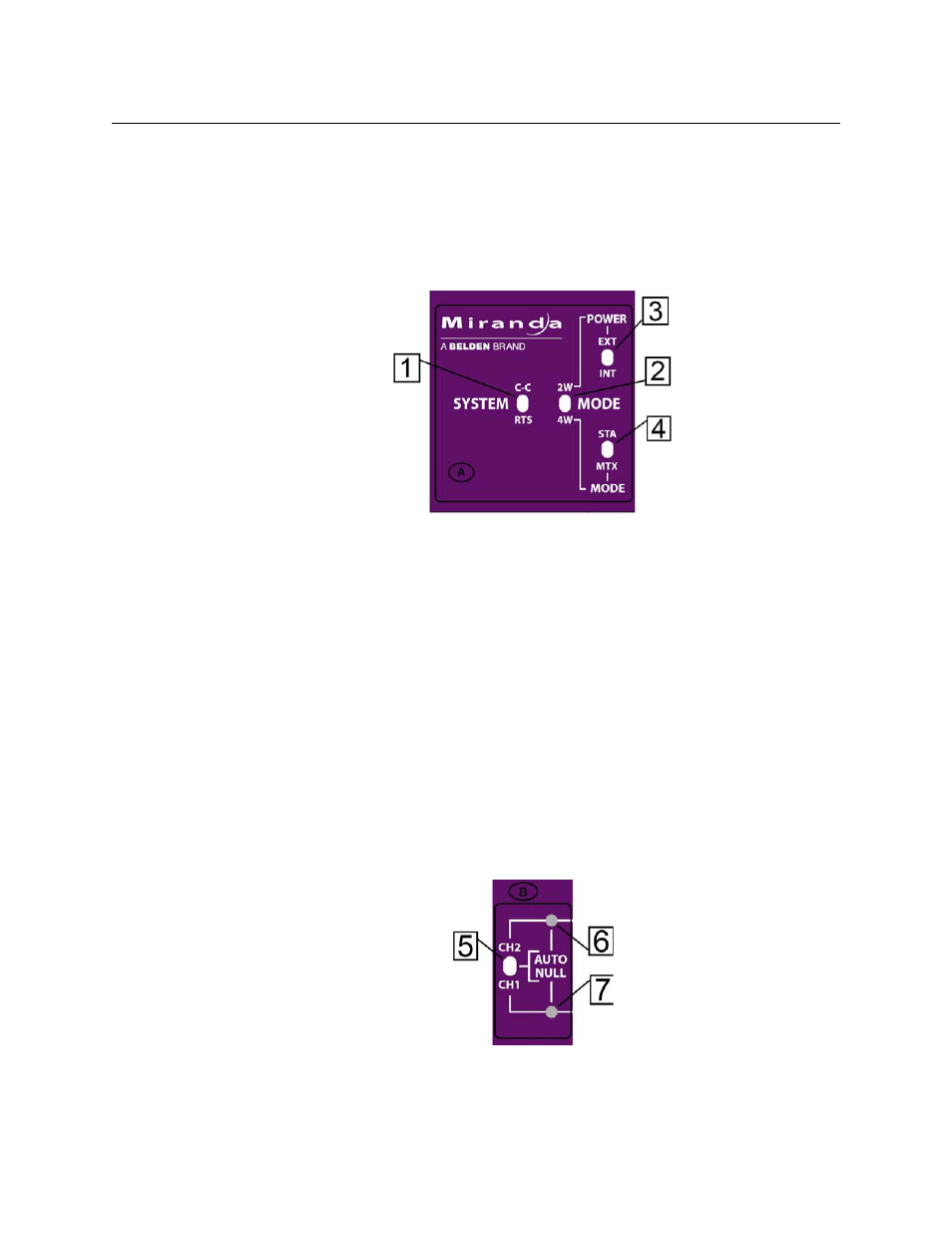
Fig. 2-5: System Configuration switches
• 1: System Switch - sets the CommLink TR6442i Fiber Optic Intercom Link in either RTS
mode or Clear-Com (C-C) mode
• 2: Mode Switch - sets the CommLink TR6442i Fiber Optic Intercom Link in either Two
Wire (2W) or Four Wire (4W) mode
• 3: 2W Power Switch - sets the CommLink TR6442i Fiber Optic Intercom Link power
mode to either externally powered (EXT) or internally powered (INT). This switch is only
operational when the Mode Switch is set to 2W.
• 4: 4W Mode Switch - sets the CommLink TR6442i Fiber Optic Intercom Link to run in
Station (STA) mode or Matrix (MTX) mode. This switch is only operational when the
Mode Switch is in 4W mode.
When connecting two CommLink TR6442i Fiber Optic Intercom Link units via fiber cable
each CommLink TR6442i Fiber Optic Intercom Link unit must be independently set for the
configuration requirements at that CommLink TR6442i Fiber Optic Intercom Link unit.
Area B - Auto Null Operation
Fig. 2-6: Auto Null switch and indicator
Please see
on page 32 below on the Auto Null function.