Grass Valley TR6442i User Manual
Page 16
12
System Overview
CommLink TR6442i Fiber Optic Intercom Link Fiber Optic Intercom Link Back Panel
CommLink TR6442i Fiber Optic Intercom Link Fiber Optic Intercom Link
Back Panel
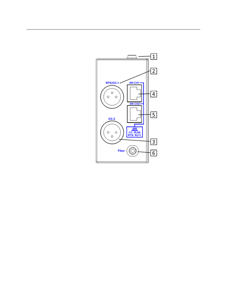
Fig. 2-8: CommLink Throw Down Back Panel
• 1: Power Connector (MTR6442i Throw Down and TR6442i Rack Mount versions only)
This connector takes a 2.5 mm locking power plug. The recommended power unit is
the ADAP-AC-04LC (see
CommLink TR6442i Fiber Optic Intercom Link Power Options
on page 16 for more information regarding CommLink TR6442i Fiber Optic Intercom
Link power options)
• 2: RTS/CC-1 Chassis Mounted XLR Connector - for RTS TW operation or Channel 1 of
Clear-Com two wire operation
• 3: CC-2 Chassis Mounted XLR Connector - for Channel 2 of Clear-Com two wire
operation. Not active when the system is in RTS-TW mode.
Connectors 4 and 5 operate in one of 4 modes, depending on system configuration.
These connectors can be used with RJ45 cables or RJ11 cables. See
Fiber Optic Intercom Link Matrix and Station Connectors
on page 14 for more
information and for wiring information.
• 4: 4W-CH1 Connector - 8 Conductor RJ45/RJ11 connector for Channel 1
• 5: 4W-CH2 Connector - 8 Conductor RJ45/RJ11 connector for Channel 2
• 6: Fiber Connector - ST Connector for Fiber Optic Cable
Read the Using Fiber Optics Guide for information on how to manage and deploy your
fiber optics cabling, safety precautions, tips & tricks, and recommendations for creating