Grass Valley 7600REF User Manual
Page 23
7600 SD/HD/MHD-REF — Instruction Manual
23
Installation
GPI Outputs 1 and 2
The General Purpose Interface (GPI) outputs 1 and 2 are configured in soft-
ware using the menus described in
GPI Outputs 1 and 2 on page 23
provide any of the following functions:
•
Loss of genlock input
•
Loss of external 10MHz reference
•
Line lock error
•
Field lock error
•
Subcarrier lock error
•
Illegal input ScH
•
Diagnostic state alert
•
Currently locked to external 10MHz
•
Currently locked to external genlock
•
Currently internal/freerun mode
The GPI outputs are single-ended open collector outputs with a
50V/200mA rating not to exceed 600 mW. The two GPI outputs are pin 17
and pin 21 as listed in
. It is intended that the GPO be
activated when one or more of the above conditions is true (for example,
loss of genlock input and/or line lock error).
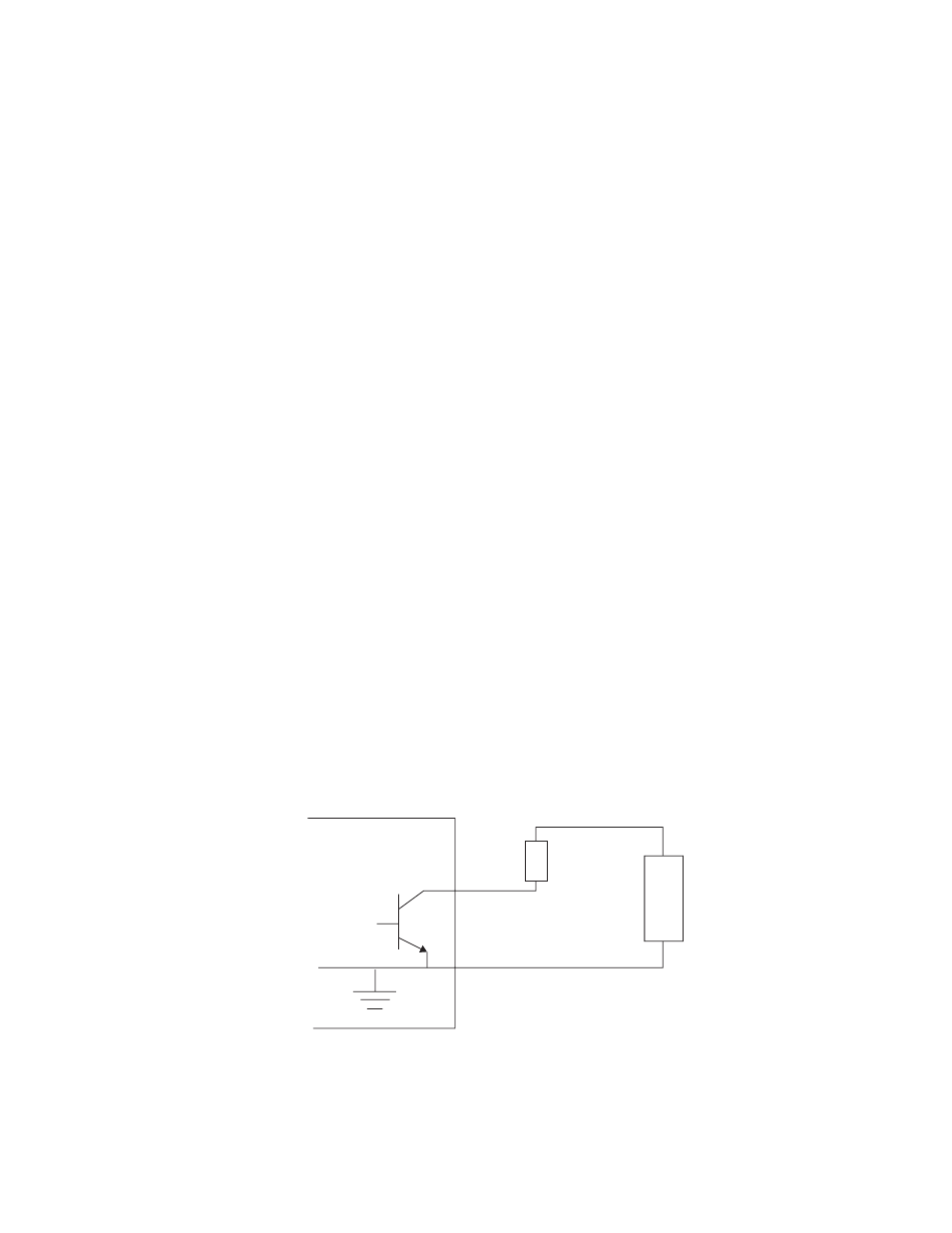
To use an output, a load should be connected between the output and an
external power supply, with the negative end of the power supply con-
nected back to the ground pin on the 25 pin Sub-D connector.
As an alternate to an external power supply, a +12V, 300mA feed is avail-
able on pin 10 of the Sub-D connector.
Figure 3. Connection to GPI Outputs
7600REF
Power Supply
+
_
Load
GPO