Grass Valley 7600REF User Manual
Page 22
22
7600 SD/HD/MHD-REF — Instruction Manual
Installation
GPI Inputs 1 and 2
The General Purpose Interface (GPI) inputs 1 and 2 are configured in soft-
ware using the menus described in
to provide
any of the following functions:
•
Force freerun mode
•
Force Genlock mode
•
Force external 10MHz lock mode
•
Step through SDI output 1 test patterns
•
Step through SDI output 2 test patterns
•
Step through SDI output 3 test patterns
•
Step through setup memories
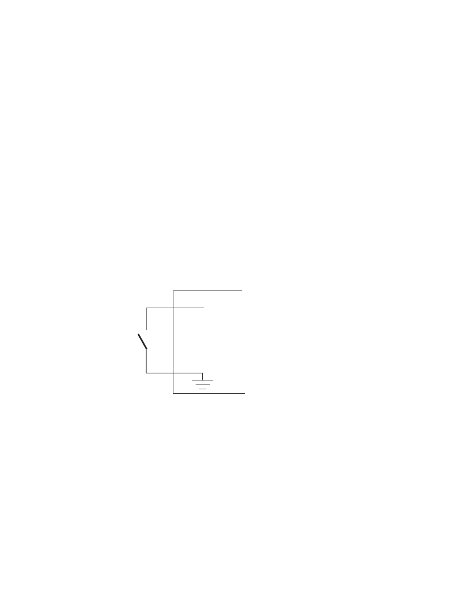
The single-ended 7600 GPI inputs are activated when connected to a
ground connection on the 25 pin Sub-D connector as shown in
.
The two GPI inputs are pin 18 and pin 19 as listed in
inputs can withstand +/- 20V and draw approximately 600uA when acti-
vated.
Figure 2. Connection to GPI Inputs
GPI In
7600Ref
See also other documents in the category Grass Valley Equipment:
- LDK 5302 (24 pages)
- SFP Optical Converters (18 pages)
- 2000GEN (22 pages)
- 2011RDA (28 pages)
- 2010RDA-16 (28 pages)
- 2000NET v3.2.2 (72 pages)
- 2000NET v3.1 (68 pages)
- 2020DAC D-To-A (30 pages)
- 2000NET v4.0.0 (92 pages)
- 2020ADC A-To-D (32 pages)
- 2030RDA (36 pages)
- 2031RDA-SM (38 pages)
- 2041EDA (20 pages)
- 2040RDA (24 pages)
- 2041RDA (24 pages)
- 2042EDA (26 pages)
- 2090MDC (30 pages)
- 2040RDA-FR (52 pages)
- LDK 4021 (22 pages)
- 3DX-3901 (38 pages)
- LDK 4420 (82 pages)
- LDK 5307 (40 pages)
- Maestro Master Control Installation v.1.5.1 (455 pages)
- Maestro Master Control Installation v.1.5.1 (428 pages)
- 7600REF Installation (16 pages)
- 8900FSS (18 pages)
- 8900GEN-SM (50 pages)
- 8900NET v.4.3.0 (108 pages)
- Safety Summary (17 pages)
- 8900NET v.4.0.0 (94 pages)
- 8906 (34 pages)
- 8911 (16 pages)
- 8900NET v.3.2.2 (78 pages)
- 8914 (18 pages)
- 8912RDA-D (20 pages)
- 8916 (26 pages)
- 8910ADA-SR (58 pages)
- 8920ADC v.2.0 (28 pages)
- 8920ADC v.2.0.1A (40 pages)
- 8920DAC (28 pages)
- 8920DMX (30 pages)
- 8920ADT (36 pages)
- 8920MUX (50 pages)
- 8921ADT (58 pages)