Power up, Indicator leds – Grass Valley 2000NET v3.2.2 User Manual
Page 17
2000NET Instruction Manual
17
Power Up
Power Up
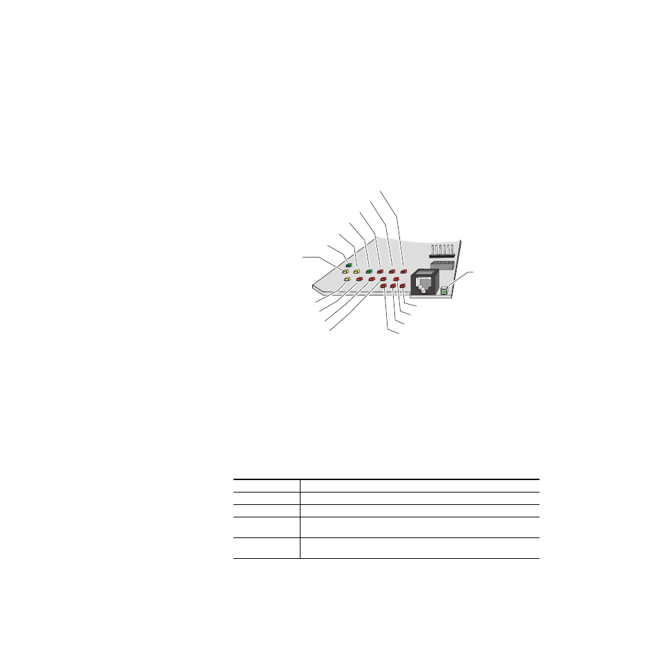
The various front LED indicators and configuration switches are illustrated
in
. Upon power-up, all LEDs should light for the duration of the
initialization process. If all LEDs remain on, the module may not be fully
seated in its slot. After initialization the Power OK LED (PWR) will be on
and the red Network Module LED (NM) should go off. All other LEDs
report detected conditions within the frame and the installed modules. If
the NM LED does not go off, the board needs servicing.
Figure 12. LEDs and Configuration Switches
The Frame Status LED is visible through the frame front cover.
describe the module LEDs and the conditions they indi-
cate.
Indicator LEDs
The frame Status LED, visible on the front cover, reports the conditions
indicated in
Table 1. Frame Status LED and Conditions Indicated
LED State
Condition
Green
Frame and all modules functioning properly. Frame locator is inactive.
Red
One or more modules in the frame has detected an internal fault. Frame locator is inactive.
Long Flash Green
Frame locator – flashes when activated by a remote control device. Green indicates frame
and all modules functioning properly.
Long Flash Alternating
Frame locator – flashes when activated by a remote control device. Alternating color indi-
cates one or more modules in the frame has detected an internal fault.
8046-02r1
Power OK (PWR) green
Remote Override (REM OVR) yellow
Power Supply 1 (PS1) red
Front Panel (FP) red
Power Supply 3 (PS3) red
Fan Health (FAN) red
Module Health (MOD) red
Frame Bus (FB) red
Ethernet (ETHER) yellow
Ethernet Link (LNK) green
Power Suppy 2 (PS2) red
Power Suppy 4 (PS4) red
Temperature (TEMP) red
Bi-color
Frame Status LED
(STATUS) red/green
Communication (COMM) yellow
Network Module (NM) red