Power up, Operation indicator leds, Ocess (see – Grass Valley 2010RDA User Manual
Page 14
8
2010/2011RDA Instruction Manual
2010/2011RDA Dual/Quad AES/EBU Reclocking DA
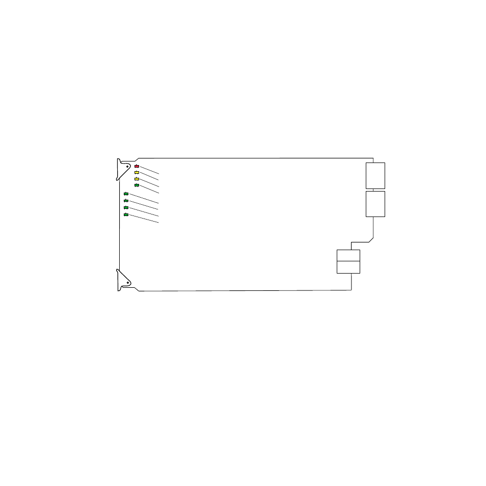
Power Up
The front LED indicators and configuration jumper are illustrated in
. Upon power-up, the green PWR LED should light and the yellow
CONF LED should illuminate for the duration of module initialization.
Operation Indicator LEDs
With valid input signals connected, the green PWR LED and the green
LOCK LED 1–4 should be on for each channel.
Figure 8. Operation Indicator LEDs
8068_03
LOCK1
FAUL
T
COMM
CONF
PWR
LOCK2
LOCK3
LOCK4
FAULT (red)
COMM (yellow)
CONF (yellow)
PWR (green)
LOCK 1 (green)
LOCK 2 (green)
LOCK 3 (green) 2011RDA only
LOCK 4 (green) 2011RDA only
This manual is related to the following products: