Engineering labels for dc power cords – H3C Technologies H3C S12500 Series Switches User Manual
Page 161
151
Content Meaning Example
ODF-MN-B-C-R/T
MN—Row number and column
number of ODF
•
M—Row number of the rack in the equipment
room, in the range of A to Z.
•
N—Column number of the rack in the
equipment room, in the range of 01 to 99.
For example, G01 is the ODF of Row G and
Column 01.
B—Row number of the terminal
device
In the range of 01 to 99, for example, 01-01.
C—Column number of the terminal
device
R—Optical receiving interface
T—Optical transmitting interface
N/A
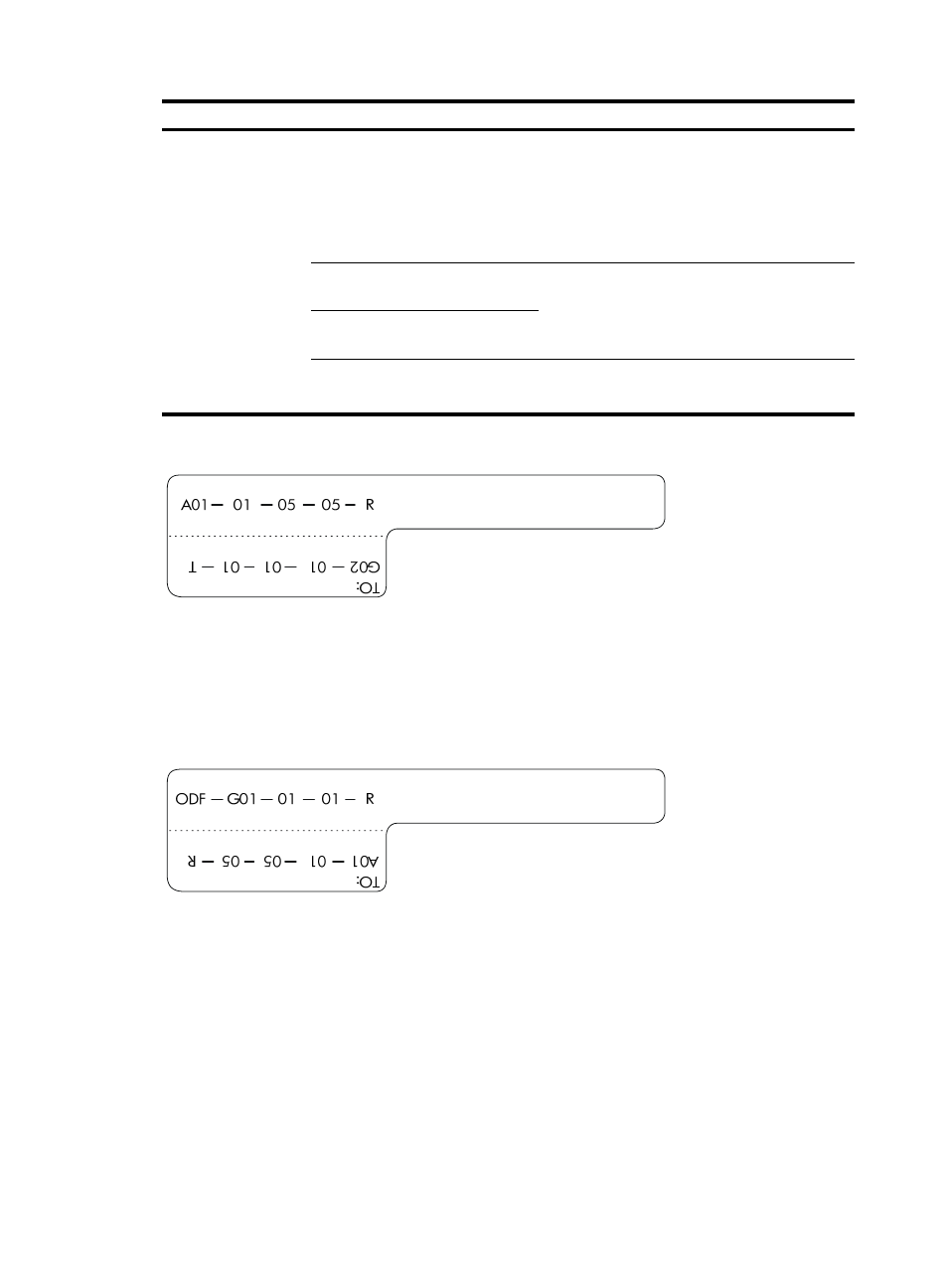
Figure 96 Example of a label on an optical fiber between two devices
•
A01-01-05-05-R—The local end of the optical fiber is connected to Optical Receiving Interface 05
on Slot 5, Chassis 01 in the rack on Row A, Column 01 in the equipment room.
•
G01-01-01-01-T—The peer end of the optical fiber is connected to Optical Transmitting Interface 01
on Slot 01, Chassis 01 in the rack on Row G, Column 01 in the equipment room
Figure 97 Example of a label on an optical fiber between the device and the ODF
•
ODF-G01-01-01-R—The local end of the optical fiber is connected to the optical receiving terminal
on Row 01, Column 01 of the ODF in Row G Column 01 in the equipment room.
•
A01-01-05-05-R—The peer end of the optical fiber is connected to Optical Receiving Interface 5 on
Slot 05, Chassis 01 in the cabinet on Row A, Column 01 in the equipment room.
Engineering labels for DC power cords
These labels are affixed to DC cables that provide power for racks, and the protection grounding cables
including the –48V, PGND, and BGND cables. The labels for DC power cords are affixed to one side of
the identification plates on cable ties.