B rear panel, B rückseite – Eneo VCQ-6057 User Manual
Page 5
5
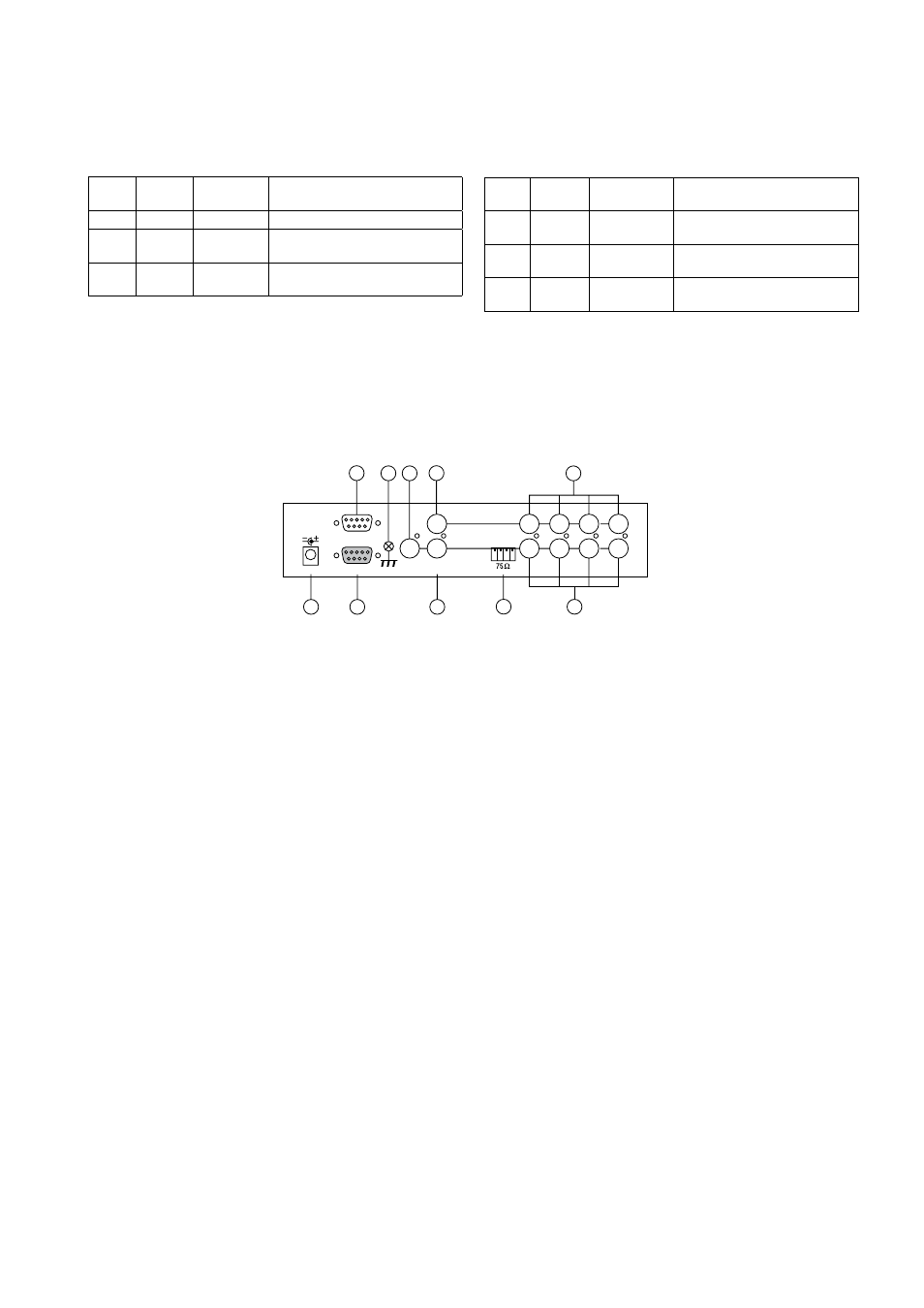
B Rear Panel
(6) Channel Select Buttons, FREEZE
When operated in full screen display mode, these buttons are used to select
specific camera to be displayed in full screen.
When operated in quad mode, these buttons are used to freeze any specific
camera by pushing the corresponding button.
(6) Standbild- / Kameraanwahl-Tasten, FREEZE
Im Vollbild-Modus bewirkt das Betätigen der Tasten die Anwahl des entsprechen-
den Kameraeinganges.
Ausgehend vom Quadbild-Modus werden, durch Betätigung dieser Tasten, in den
jeweiligen Quadranten Standbilder erzeugt (Einfrieren).
B Rückseite
hi-z
3 4
DC V amp
RS-3
ALARM I/O
in
out
5
9
8
0
3
6
7
monitor
vcr
7
Die v.g.Tasten dienen auch zur Cursor-Bewegung sowie Text-Zeichenauswahl im
Bildschirm-Menü.
These buttons are also used as cursor control and text select keys under setup
menu mode.
(7) Erdungs - Anschluss
Vorgesehen zum Anschluss der Betriebserde.
(8) Spannungsversorgung
Anschluss des mitgelieferten Netzadapters (VDC)
(9) Fernbedienungs-/RS-232 - Anschluss
Anschluss für die jeweils vorgesehene Fernbedienung (s. Abschnitt 8/Zubehör),
bzw. zur Geräte-Konfiguration über einen PC (s. Abschnitt 7).
(10) Alarm-Eingang (Alarm in)
9-pol. D-Sub-Buchse für den Anschluss der Alarm Ein-/Ausgangs-Kontakte.
Als Alarm-Ausgang ist ein Relais-Umschaltkontakt vorhanden.
Pin - Belegung des Alarmanschlusses
Pin-Nr.
Pin-Nr.
Pin-Nr.
Eingang
4 Eingang 4
7 Schliess-Kontakt
Eingang
5 Reset
8 Gemeinsam
3 Eingang 3
6 Masse
9 Öffner-Kontakt
(11) Eingangs-Abschluss
Impedanz-Schalter für jeden Kamera-Eingang, schaltet zwischen 75Ohm und
HI-Z Impedanz. Ein falscher Abschluss setzt die Qualität des Videosignals
herunter. Der Abschluss ist werkseitig auf 75Ohm gesetzt.
(12) Videoeingänge
BNC-Eingänge zum Anschluss der Kameras -4.
Im Quad-Modus werden die vier Eingänge wie folgt dargestellt:
(7) Chassis GND
This contact is provided to ground the chassis to the Earth Ground to prevent
interference and electrical shock.
(8) Power Input
Power input connector. Use DC VDC
(9) Remote/RS-232 Connector
This 9 pin D-sub connector is used to provide remote control operation via the
appropriate remote keypad (see section 8/Accessories) or a PC.
Please refer to section 7 for more details.
(10) Alarm In
This 9 pin D-sub connector is used for alarm sensor input and alarm output
control connections. It provides Normally open and Normally closed contacts for
alarm out control.
Pin assignment for alarm connector
Pin #
Pin #
Pin #
Sensor
4 Sensor 4
7 Normally open contact
Sensor
5 Reset
8 Common contact
3 Sensor 3
6 GND
9 Normally closed contact
(11) Terminations
These impedance switches are used to provide proper termination for each ca-
mera input. These switches toggle between 75ohms and Hi-Z impedance. Incor-
rect termination will degrade the quality of the video signal. All video inputs not
„looped through” to another device, the corresponding switches need to be set
to 75ohms termination position. If another device is connected to video out loop
through connector, set the corresponding termination switch to Hi-Z position. Any
device connected to the video out loop through connectors needs to be configure
to 75ohms. video termination. The factory default termination setting is 75ohms.
Video
Freeze
Quad
Taste (5)
Kanal-An-
wahltaste (6)
Funktion
EIN
EIN
EIN
Das Quadrantenbild wird eingefroren.
EIN
AUS
EIN
Darstellung des eingefrorenen Bildes im
Vollbild-Modus
AUS
EIN/AUS
EIN
Darstellung des Kameraeinganges im
Vollbild-oder Quad-Modus
Video
Freeze
Quad
button (5)
Channel select
buttons (6)
Function
ON
ON
ON
Freeze specific camera video in quad
screen mode
ON
OFF
ON
Call up specific camera input in
Freeze mode
OFF
ON/OFF
ON
Call up specific camera input in Full
screen mode