7 vcr operations, 7 vcr-betrieb, Fernbedienbetrieb – Eneo VCQ-6057 User Manual
Page 15: Remote control operations, 1 pin assignment of the 9 pin d-sub connector
5
6.7 VCR Operations
6.7.1 Connecting the Record and Stop switch connectors from a VCR to the alarm
out contact in the 9-pin D-sub connector will allow user to use an ordinary VCR
to record only when an alarm is triggered.
Please refer to section 5.3 for detail connection.
6.7.2 Zoom on VCR playback operation
Push
VCR button (3) to ON will switch the device to VCR playback mode. Under
this mode, if the device is on quad display mode, a pre-recorded quad display vi-
deo in the tape will be shown on the screen. If the device is in full screen display
mode, push any channel select buttons
(6) will select and expand the correspon-
ding quadrants of the pre-recorded video to full screen display.
6.7 VCR-Betrieb
6.7.1 Der Anschluss der Fernbedien-Funktionen Aufzeichnung und Stop eines
Videorekorders an den Schaltausgang des Quad-Splitters ermöglicht, dass der
Rekorder automatisch das Bild einer alarmierten Kamera aufzeichnet (Verkabe-
lung s. Abschnitt 5.3).
6.7.2 Vergrößerung der Quadranten-Bilder bei VCR-Wiedergabe
(Zoom-Funktion)
Mit der Taste
(3) auf VCR-Wiedergabe schalten und das aufgezeichnete Quad-
Bild wiedergeben. Voraussetzung für ein Zoomen der Quadrantenbilder auf
Vollbild-Format ist die Betriebsart „Vollbild”, Taste
(6).
Taste
(5). Die Auswahl, welches Quadrantenbild als Vollbild dargestellt werden
soll, geschieht mit den Anwahl-Tasten
(6).
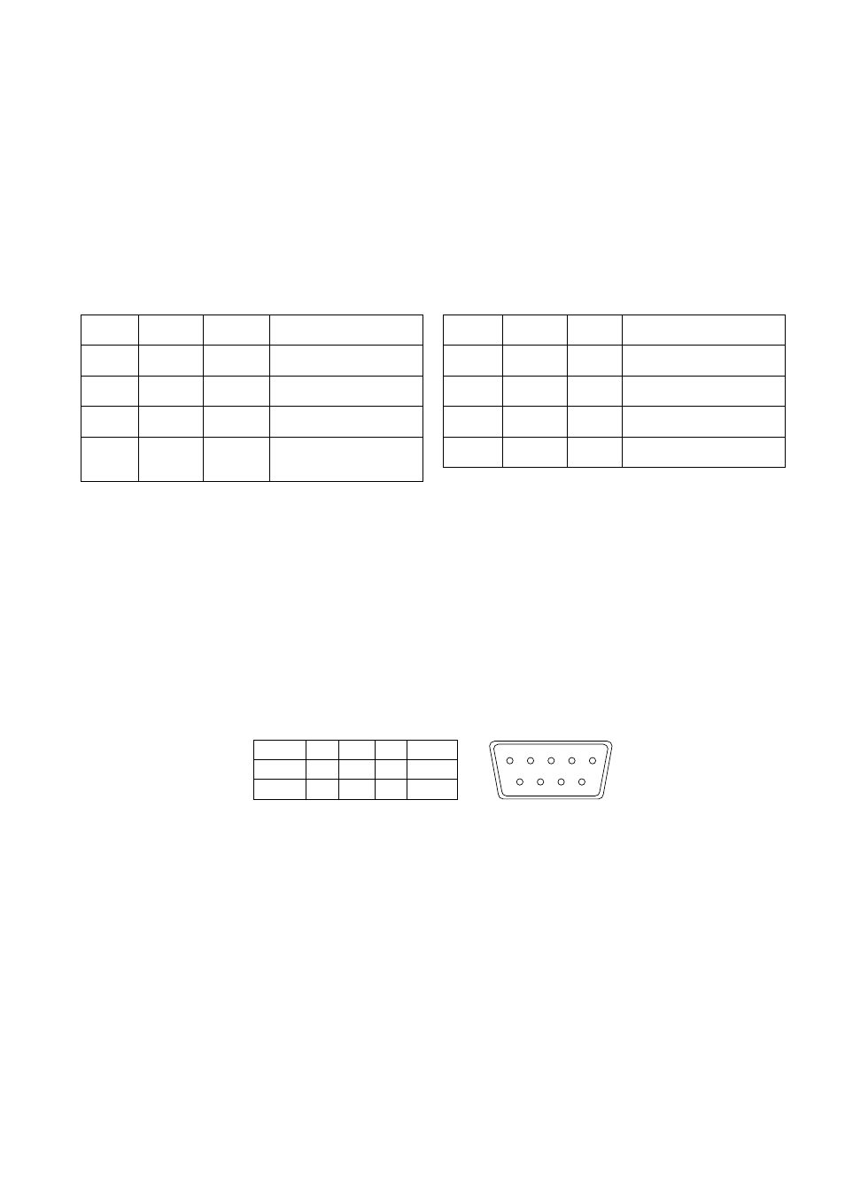
Steckerseite (Male type)
Bei den, zu den jeweiligen Geräte-Modellen passenden Kabel-Fernbedienungen
(s. Abschnitt 8/Zubehör), werden über die Pins , und 3 die Steuersignale
geführt und über die Pins 5, 6, 7, 8 und 9 die Spannungsversorgung.
Hinweis: Wird zur Steuerung ein PC benutzt, unter Verwendung der RS-3-
Schnittstelle, dürfen die Pins 6, 7, 8 und 9 nicht angeschlosssen werden.
Für die Übertragung der Steuersignale sind ausschließlich die Pins , und 3 zu
benutzen. Über die Fernbedienung sind die gleichen Funktionen steuerbar, wie
über die normale Frontbedienung.
When a remote keypad is used to control the device, pin , and 3 are used for
control signals transmission, pin 6, 7, 8 and 9 are used for providing power to the
remote keypad.
Note: If a computer device is used to control this unit through a RS-3 port,
pin 6, 7, 8 and 9 must be disconnected to prevent connecting the Vcc and GND
signals from the device to the computer. A RS-3 port only uses pin , and
3 for control signal transmission. If a remote keypad is connected to the 9 pin
D-sub connector, all the control functions provided in the front panel will be also
available from the keypad.
A terminal or computer can be connected to the male type 9 pin D-sub connector
on the rear panel from it’s RS-3 port to control this device using standard
uppercase ASCII codes. The ASCII command codes for the quad are available
upon request. The interface protocol consists of 8 data bit, start bit, stop bit,
no parity and the transmission is 00 baud.
GND
4
NC
7
VCC
RX
5
NC
8
GND
3 TX
6
VCC
9
GND
5
9
4
8
3
7
6
VCR-Taste
(7)
Quad-Taste
(5)
Kanaltasten
(6)
Funktion
EIN
EIN
AUS
Darstellung des aufgezeichneten
Quadbildes
EIN
AUS
x
Vergrößerte Quadrantenbild-
Darstellung
EIN
AUS
x
Einfrieren des vergrößerten
Quadrantenbildes
AUS
X
X
VCR-Wiedergabe über das Gerät
beenden, Rückkehr in die zuvor
angewählte Betriebsart
VCR button
(7)
Quad button
(5)
CH select
button (6)
Function
ON
ON
OFF
Display quad video signal from VCR
tape
ON
OFF
Push once Call up specific quadrant from tape
in full screen mode
ON
OFF
Push twice Freeze specific quadrant from tape
in full screen mode
OFF
X
X
Exit VCR operation, back to normal
operating mode
7. Fernbedienbetrieb
Über den 9-pol. D-Sub Fernbedien-Anschluss 9 (Remote or RS-3) kann das
Gerät mittels einer Kabel-Fernbedienung (s. Abschnitt 8/Zubehör) oder eines PC’s
ferngesteuert werden (ASCII-Code).
7.1 Belegung der 9-pol. D-Sub-Buchse (Remote/RS-232)
Pin-Belegung des Fernbedien-Anschlusses
7. Remote Control Operations
The device may be controlled via the 9 pin D-sub/RS-3 connector from a
appropriate keypad (see section 8/accessories), or a PC using ASCII code.
7.1 Pin Assignment of the 9 pin D-Sub Connector
Pin assignment for remote control connector