Figure 5-3. normal operation -3, Ee figure 5-3), Hazardous area oxymitter 4000 – Emerson Process Management OXYMITTER 4000 User Manual
Page 77: Instruction manual
Instruction Manual
IB-106-340C Rev. 4.1
July 2004
Rosemount Analytical Inc. A Division of Emerson Process Management
Startup and Operation with Keypad 5-3
Hazardous Area Oxymitter 4000
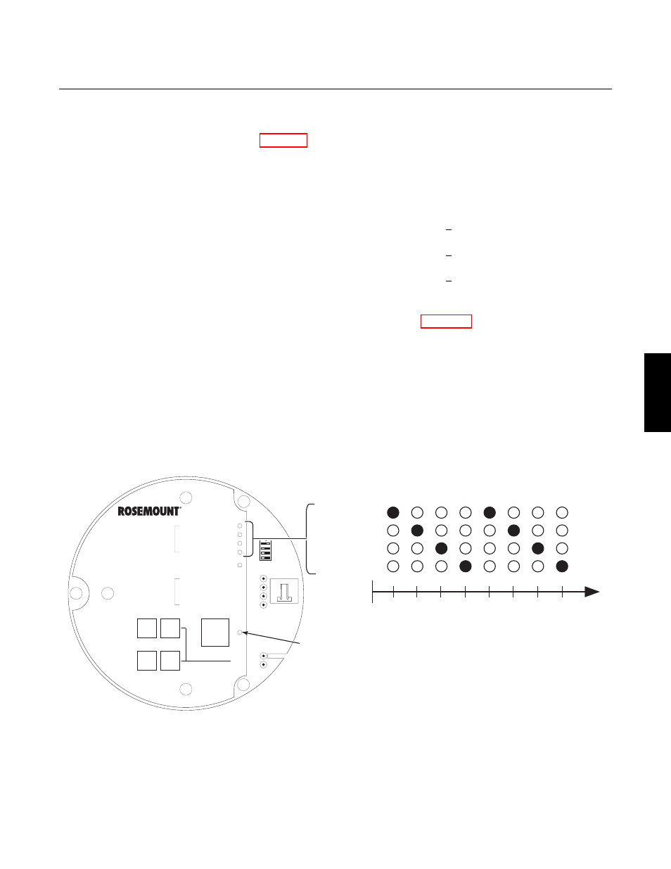
4. CAL LED. The CAL LED is on steady
or flashing during calibration. Further
information is available in Section 9,
MAINTENANCE AND SERVICE.
5. Keys.
(a) INC and DEC. The INC and DEC
keys are used to set the values of
the calibration gases. Attach a
multimeter across TP5 and TP6.
The calibration and process gases
can now be monitored. Pressing
the INC or DEC once will cause
the output to switch from the proc-
ess gas to the calibration gas.
Pressing INC or DEC a second
time will increase or decrease the
calibration gas parameter. If the
keys have been inactive for one
minute, the output reverts to the
process gas. When a calibration
has been initiated, the value at
TP5 and TP6 is the % O
2
seen by
the cell.
Oxygen levels, as seen on the
multimeter, are:
8.0% O
2
= 8.0 volts DC
0.4% O
2
= 0.4 volts DC
(b) CAL. The CAL key can:
1 Initiate a calibration.
2 Sequence through calibration.
3 Abort
the
calibration.
NOTE
Refer to Section 9, MAINTENANCE AND
SERVICE, for calibration instructions.
b. Model 751 Remote Powered Loop
LCD Display (Optional)
Refer to Remote Powered Loop LCD
manual for calibration and operation.
HEATER T/C
HEATER
O CELL
2
CALIBRATION
LIGHTING SEQUENCE DURING NORMAL OPERATION
1
2
3
4
1
2
3
4
DIAGNOSTIC
ALARMS
TEST
POINTS
HEATER T/C
HEATER
O2 CELL
CALIBRATION
CALIBRATION RECOMMENDED
O2 CELL mV +
O2 CELL mv -
HEATER T/C +
HEATER T/C -
INC
INC
DEC
DEC
HIGH
GAS
LOW
GAS
CAL
TEST GAS +
PROCESS -
% O2
SW2
TP1
J1
TP2
TP3
RED
YEL
GRN
ORG
TP4
TP5
TP6
ON
CAL LED
22220055
Figure 5-3. Normal Operation
5