Hazardous area oxymitter 4000, Instruction manual – Emerson Process Management OXYMITTER 4000 User Manual
Page 36
Instruction Manual
IB-106-340C Rev. 4.1
July 2004
1-6 Description and Specifications
Rosemount Analytical Inc. A Division of Emerson Process Management
Hazardous Area Oxymitter 4000
(d) Optional IMPS 4000. The Pro-
grammable Logic Controller (PLC)
in the IMPS 4000 provides fault
indications using flashing LEDs
and LCD display messages. Refer
to the IMPS 4000 Intelligent Multi-
probe Test Gas Sequencer manual
for more information.
10. The optional Rosemount 751 remote
mounted LCD display panel is loop-
driven by the 4-20 mA output signal
representing the O
2
percentage.
e. Handling the Hazardous Area
Oxymitter 4000
It is important that printed circuit
boards and integrated circuits are
handled only when adequate antistatic
precautions have been taken to pre-
vent possible equipment damage.
The Hazardous Area Oxymitter 4000 is
designed for industrial applications.
Treat each component of the system
with care to avoid physical damage.
Some probe components are made
from ceramics, which are susceptible
to shock when mishandled.
f. System
Considerations
Prior to installing your Hazardous Area
Oxymitter 4000, make sure you have all the
components necessary to make the system
installation. Ensure all the components are
properly integrated to make the system
functional.
After verifying that you have all the compo-
nents, select mounting locations and deter-
mine how each component will be placed
in terms of available line voltage, ambient
temperatures, environmental considera-
tions, convenience, and serviceability.
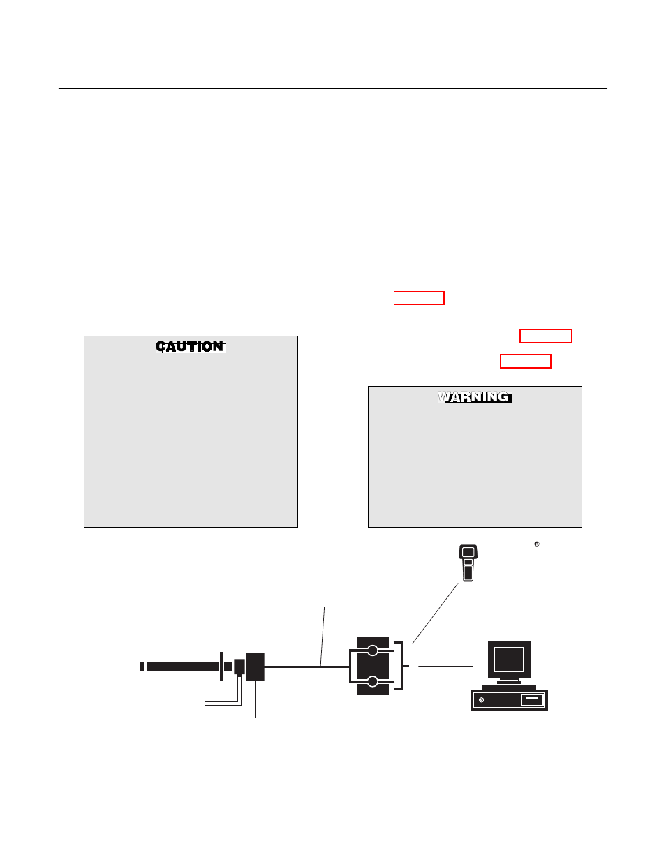
Figure 1-5 shows a typical system wiring.
A typical system installation with integral
electronics is illustrated in Figure 1-6. A
typical system installation with remote elec-
tronics is illustrated in Figure 1-7.
The HART option is not protected by
energy limiting barriers. It must not be
interfaced from within the hazardous
area. The 4-20 mA cables should be
routed and the connections made out-
side the hazardous area. Note that this
is the case even when using the in-
trinsically safe version of the handheld
communicator.
LINE VOLTAGE
2 CALIBRATION GAS LINES
BY CUSTOMER
[300 FT (90 M) MAX]
HAZARDOUS AREA
OXYMITTER 4000
WITH INTEGRAL ELECTRONICS
TERMINATION IN
CONTROL ROOM
ASSET MANAGEMENT SOLUTIONS
4-20 MA OUTPUT
(TWISTED PAIR)
HART
MODEL 275/375
HAND HELD
INTERFACE
37270009
Figure 1-5. Hazardous Area Oxymitter 4000 HART Connections and AMS Application