Hazardous area oxymitter 4000, Instruction manual – Emerson Process Management OXYMITTER 4000 User Manual
Page 65
Instruction Manual
IB-106-340C Rev. 4.1
July 2004
Rosemount Analytical Inc. A Division of Emerson Process Management
Configuration with Keypad 3-3
Hazardous Area Oxymitter 4000
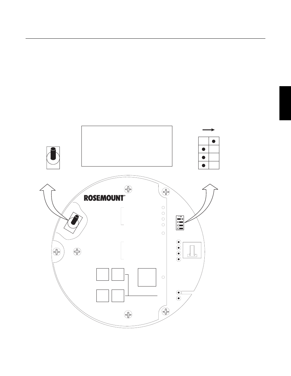
1. Access TP5 and TP6 next to the mem-
brane keypad. Attach a multimeter
across TP5 and TP6. The calibration
and process gases can now be moni-
tored. Pressing the INC or DEC once
will cause the output to switch from the
process gas to the calibration gas.
Pressing INC or DEC a second time
will increase or decrease the calibra-
tion gas parameter. If the keys have
been inactive for one minute, the
output reverts to the process gas.
When a calibration has been initiated,
the value at TP5 and TP6 is the %O
2
seen by the cell. Oxygen levels, as
seen on the multimeter, are:
8.0% O
2
= 8.0 VDC
0.4% O
2
= 0.4 VDC
2. HART/AMS.
3. Model 751. The loop-driven LCD
display.
DIAGNOSTIC
ALARMS
TEST
POINTS
HEATER T/C
HEATER
O2 CELL
CALIBRATION
CALIBRATION RECOMMENDED
O2 CELL mV +
O2 CELL mV -
HEATER T/C +
HEATER T/C -
INC
INC
DEC
DEC
HIGH
GAS
LOW
GAS
CAL
TEST GAS +
PROCESS -
% O2
SW2
SW1
TP1
J1
TP2
TP3
RED
YEL
GRN
ORG
TP4
TP5
TP6
ON
4-20 mA IS
INTERNALLY
POWERED (DEFAULT)
4-20 mA REQUIRES
EXTERNAL POWER
HART
0 TO 10% O
2
3.5 mA
220 V
115 V
0 TO 25% O
2
LOCAL
21.6 mA
DEFAULT
POSITION
(EX-FACTORY)
3.5 mA/21.6 mA:
0 TO 25% O :
2
0 TO 10% O /
2
LOCAL:
HART: O RANGE SET BY HART/AMS
(FROM 0 TO 40% O )
O RANGE SET BY POS 2
O RANGE
WHEN ALARM EXISTS, OR ON
POWER-UP, OUTPUT CURRENT
GOES TO THIS VALUE
2
2
2
2
1
2
3
4
37270001
ON
OFF
NOTE:
THE 115 V OPTION AT
SWITCH SW2 POSITION 4
IS ACTIVE ONLY WHEN
THE HEATER VOLTAGE
OPTION IS SET TO MANUAL
IN THE SOFTWARE
(AUTO TUNE = NO).
Figure 3-2. Defaults – Hazardous Area Oxymitter 4000 with Membrane Keypad
3