Figure 9-5. electronic assembly -10, Hazardous area oxymitter 4000, Instruction manual – Emerson Process Management OXYMITTER 4000 User Manual
Page 128
Instruction Manual
IB-106-340C Rev. 4.1
July 2004
9-10 Maintenance and Service
Rosemount Analytical Inc. A Division of Emerson Process Management
Hazardous Area Oxymitter 4000
(f) Restore power to the system; refer
to paragraph 5-1 or 6-1. When the
probe is at operating temperature,
calibrate the probe per paragraph
9-2.
NOTE
Recalibration is required whenever
electronic cards or sensing cell is
replaced.
b. Replacement of Entire Electronics
(with Housing) – Hazardous Area
Oxymitter 4000 with Integral Electronics.
1. Follow the instructions in paragraph
9-4a to remove the Hazardous Area
Oxymitter 4000 probe from the stack
or duct.
Do not force the probe housing when
installing or removing from the inte-
gral electrical barrier/feedthrough
(Figure 9-3). Damage to the aluminum
probe housing can occur.
2. Remove four screws (22, Figure 9-3)
and washers (21) from the probe tube
assembly (23). Remove the probe tube
assembly from the housing (11).
3. Disconnect the heater and signal wire
connectors from the mating connectors
on the heater strut assembly (32).
NOTE
The integral electrical barrier/feed-
through is thread-locked into the elec-
trical housing and cannot be
removed.
4. Make sure the O-ring (31) is in good
condition. Replace O-ring if damaged.
5. Make sure that the conduit port of the
electronic housing is on the same side
as the CAL and REF gas ports. Install
four washers (21) and screws (22).
Tighten screws.
6. Follow the instructions in paragraph
2-1b to install the Hazardous Area
Oxymitter 4000 into the stack or duct.
Opening the electronic housing will
cause the loss of ALL hazardous per-
mits. Opening the electronics housing
in hazardous areas may cause an
explosion resulting in loss of property,
severe personal injury, or death. It
may be required to get a hot work
permit from your company safety offi-
cer before opening the electronic
housing.
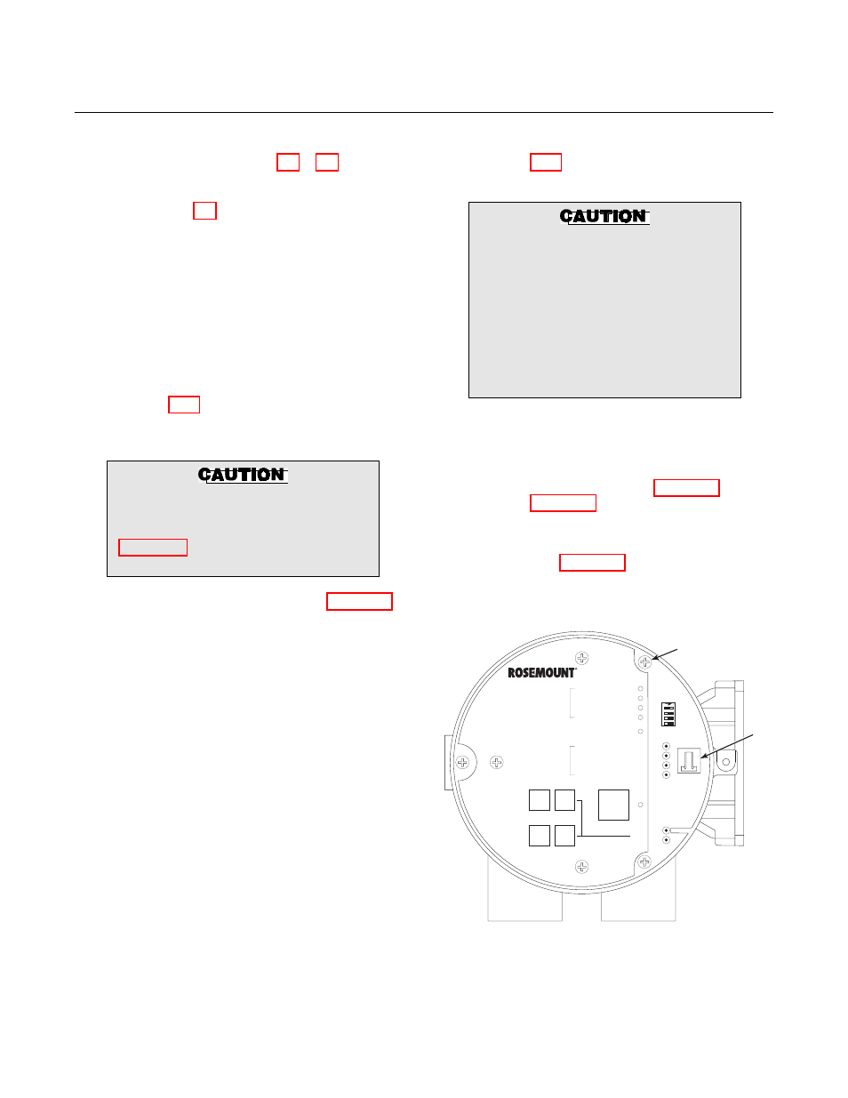
c. Electronic
Assembly
Replacement
Remove and replace the electronic assem-
bly according to the following procedure.
1. Remove screw (18, Figure 9-3 or
Figure 9-4), cover lock (19), and cap-
tive washer (20) securing cover (1).
Remove the cover.
2. See Figure 9-5. Depress and remove
the J1 (cell and T/C) connector from
the J1 socket.
DIAGNOSTIC
ALARMS
TEST
POINTS
HEATER T/C
HEATER
O2 CELL
CALIBRATION
CALIBRATION RECOMMENDED
O2 CELL mV +
O2 CELL mv -
HEATER T/C +
HEATER T/C -
INC
INC
DEC
DEC
HIGH
GAS
LOW
GAS
CAL
TEST GAS +
PROCESS -
% O2
SW2
TP1
J1
TP2
TP3
RED
YEL
GRN
ORG
TP4
TP5
TP6
ON
J1
MOUNTING
SCREW
37270018
Figure 9-5. Electronic Assembly