8, figure 9-3), Figure 9-3), 17, figure 9-3 – Emerson Process Management OXYMITTER 4000 User Manual
Page 126: 8, figure 9-3, Figure 9-3, 18, figure 9-3 or, Figure, 3 or, Hazardous area oxymitter 4000, Instruction manual
Instruction Manual
IB-106-340C Rev. 4.1
July 2004
9-8 Maintenance and Service
Rosemount Analytical Inc. A Division of Emerson Process Management
Hazardous Area Oxymitter 4000
37270004
DIAGNOSTIC
ALARMS
TEST
POINTS
HEA
TER
T/C
HEA
TER
02
CELL
CALIBRA
TION
CALIBRA
TION
RECOMMENDED
02
CELL
mV
+
02
CELL
mv
-
HEA
TER
T/C
+
HEA
TER
T/C
-
INC
INC
DEC
DEC
HIGH
GAS LO
W
GAS
CAL
TEST
GAS
+
PROCESS
-
% 02
35
23
34
17A
10
18
18
20
20
19
19
9
3
4
6
7 8
11
12
13
14
15
16
17
2
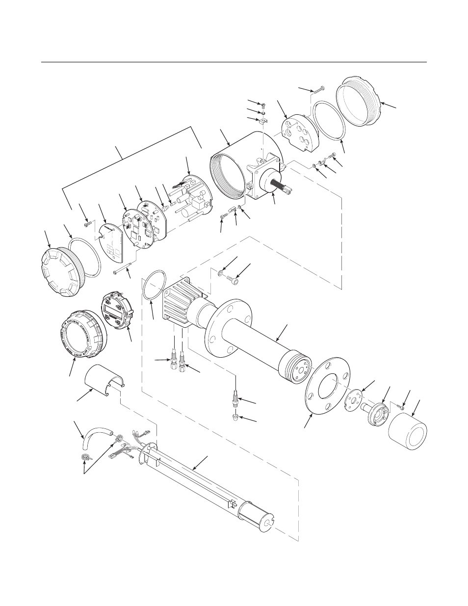
Note: Not all parts shown.
30
29
29
29
32
25
24
26
27
28
33
22
21
4A
1A
Note: The Electronic Assembly, item 2,
consists of items 3 through 10.
1
17A
1. Blind Cover
1A. Window Cover
2. Electronic Assembly
3. Screw
4. Membrane Keypad
4A. LOI Module
5. Microprocessor Board
6. Analog Board
7. Fuse Cap
8. Fuse
9. Power Supply Board
10. Captive Screw
11. Housing
12. Screw
13. Lock Washer
14. Cable Clamp
15. Terminal Block
16. Captive Screw
17. Blind Cover
17A. O-Ring
18. Screw
19. Cover Lock
20. Captive Washer
21. Washer
22. Screw
23. Probe Tube Assembly
24. Gasket
25. Corrugated Seal
26. Cell and Flange
Assembly
27. Retainer Screw
28. Flame Arrester with
Snubber Diffuser
29. Flame
Arrestor Fitting
30. Cap
31. O-Ring
32. Heater Strut Assembly
33. Tube Clamp
34. Silicon Tube
35. Strut Pressure Clamp
5
31
7 8
Integral
Electrical
Barrier/
Feedthrough
Figure 9-3. Hazardous Area Oxymitter 4000 with Integral Electronics – Exploded View