Figure 9-2. inside right cover -4, Hazardous area oxymitter 4000, Instruction manual – Emerson Process Management OXYMITTER 4000 User Manual
Page 122: Alarms manual calibration
Instruction Manual
IB-106-340C Rev. 4.1
July 2004
9-4 Maintenance and Service
Rosemount Analytical Inc. A Division of Emerson Process Management
Hazardous Area Oxymitter 4000
SW2 DIP SWITCH
HART
LOCAL
0-10%
0-25%
4mA
20mA
NOT USED
NOT USED
LED
HEATER
O2 CELL
CALIBRATION
HEATER T/C
STATUS
OPEN
SHORTED
REVERSED
HIGH HIGH
TEMP
HIGH CASE
TEMP
LOW TEMP
HIGH TEMP
OPEN
BAD
EPROM
CORRUPT
INVALID SLOPE
INVALID
CONSTANT
FLASHES
1
2
3
4
1
2
OPEN
3
4
5
1
3
4
1
2
PUSH CAL
CAL LED ON
APPLY TG1
PUSH CAL
CAL LED ON SOLID
REMOVE TG1 & APPLY TG2
PUSH CAL
CAL LED ON SOLID
WAIT FOR FLASH
REMOVE TG2
PUSH CAL
1
2
3
4
5
6
7
ALARMS
MANUAL
CALIBRATION
CAL LED ON FOR
PURGE TIME
WAIT FOR FLASH
CAL LED OFF
PUSH CAL
CAL LED FLASH
2 FLASH-VALID CAL
3 FLASH-INVALID CAL
8
PLACE CONTROL LOOP
IN MANUAL
IF CAL LED ON
GO TO STEP 2
*
*
3
LAST CAL
FAILED
A/D COMM
ERROR
29770005
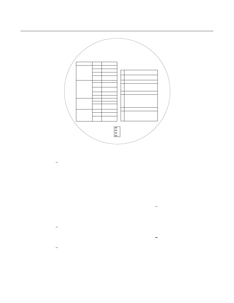
Figure 9-2. Inside Right Cover
2 Push the CAL key. The CALI-
BRATION RECOMMENDED
LED will turn off and the CAL
LED will flash continuously.
The Hazardous Area Oxymit-
ter 4000 can be configured
so that the 4-20 mA signal
will hold the last value. The
default condition is for the
output to track. A flashing LED
indicates that the Hazardous
Area Oxymitter 4000 is ready
to accept the first calibration
gas.
3 Apply the first calibration gas.
(Electronics will abort the cali-
bration if step 4 is not done
within 30 minutes).
4 Push the CAL key; the CAL
LED will be on solid. A timer is
activated to allow the calibra-
tion gas adequate time to flow
(default time of five minutes).
When the timer times out, the
Hazardous Area Oxymitter
4000 has taken the readings
using the first calibration gas
and the CAL LED will flash
continuously. The flashing
indicates the Hazardous Area
Oxymitter 4000 is ready to
take readings using the sec-
ond calibration gas.
5 Remove the first calibration
gas and apply the second
calibration gas. (Electronics
will abort the calibration if
step 6 is not done within 30
minutes).
6 Push the CAL key; the CAL
LED will be on solid. The timer
is activated for the second
calibration gas flow. When the
timer times out, the CAL LED
will flash a 2 pattern flash or a
3 pattern flash (2 pattern flash
equals a valid calibration, 3
pattern flash equals an invalid