Figure 8-4. fault 2, shorted thermocouple -6, Hazardous area oxymitter 4000, Alarms o2 t/c shorted – Emerson Process Management OXYMITTER 4000 User Manual
Page 102: Instruction manual
Instruction Manual
IB-106-340C Rev. 4.1
July 2004
8-6 Troubleshooting
Rosemount Analytical Inc. A Division of Emerson Process Management
Hazardous Area Oxymitter 4000
Alarms
O2 T/C Shorted
LOI
KEYPAD
DIAGNOSTIC
ALARMS
TEST
POINTS
HEATER T/C
HEATER
O2 CELL
CALIBRATION
CALIBRATION RECOMMENDED
O2 CELL mV +
O2 CELL mv -
HEATER T/C +
HEATER T/C -
INC
INC
DEC
DEC
HIGH
GAS
LOW
GAS
CAL
TEST GAS +
PROCESS -
% O2
SW2
TP1
J1
TP2
TP3
RED
YEL
GRN
ORG
TP4
TP5
TP6
ON
37260020
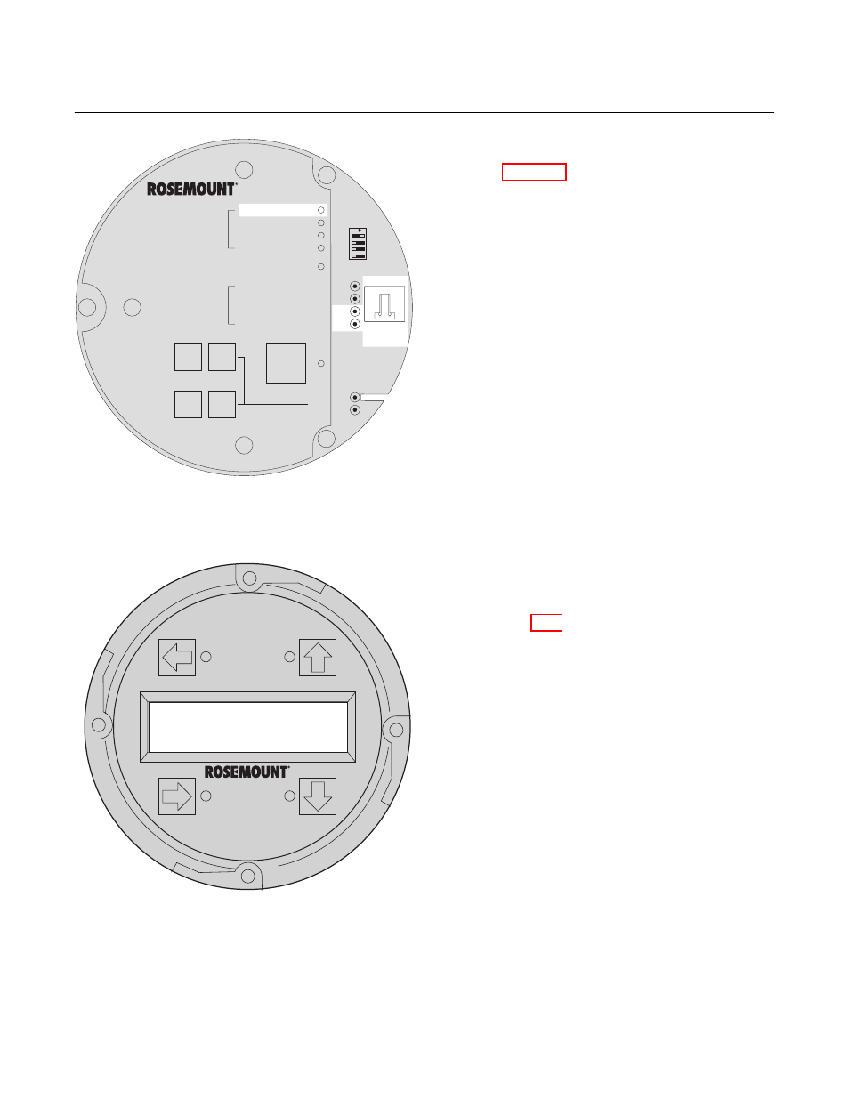
Figure 8-4. Fault 2, Shorted Thermocouple
b. Fault 2, Shorted Thermocouple
Figure 8-4 shows the electronic assembly
for a Hazardous Area Oxymitter 4000 with
a membrane keypad (upper view) and a
Hazardous Area Oxymitter 4000 with an
LOI (lower view). The upper view also
shows J1 and test points TP1 through TP6,
located on the microprocessor board, below
the membrane keypad or the LOI module.
Membrane Keypad. When Fault 2 is
detected, the HEATER T/C LED flashes
twice, pauses for three seconds, and
repeats.
1. Using a multimeter, measure the volt-
age from TP3+ to TP4-. If the reading
is 0 ±0.5 mV, then a shorted thermo-
couple is likely.
2. Remove power and disconnect J1.
3. Measure the resistance from TP3+
to TP4-. The reading should be ap-
proximately 20K ohms.
4. If so, the short is not on the PC board.
The thermocouple wiring or the ther-
mocouple is shorted. See paragraph
9-4g, Heater Strut Replacement.
LOI. When Fault 2 is detected, the LOI
displays the “O2 T/C Shorted” message.
1. Remove power. Unscrew and remove
the LOI module from the electronic
assembly.
2. Reconnect power to the Oxymitter
4000.
3. Perform the diagnostic steps 1 through
4 shown for the membrane keypad.