Watson-Marlow 624Di User Manual
Page 9
Watson-Marlow Bredel E-Manuals
http://www.watson-marlow.it/pdfs-global/m-624Di-gb-01.htm[10/07/2012 13:59:15]
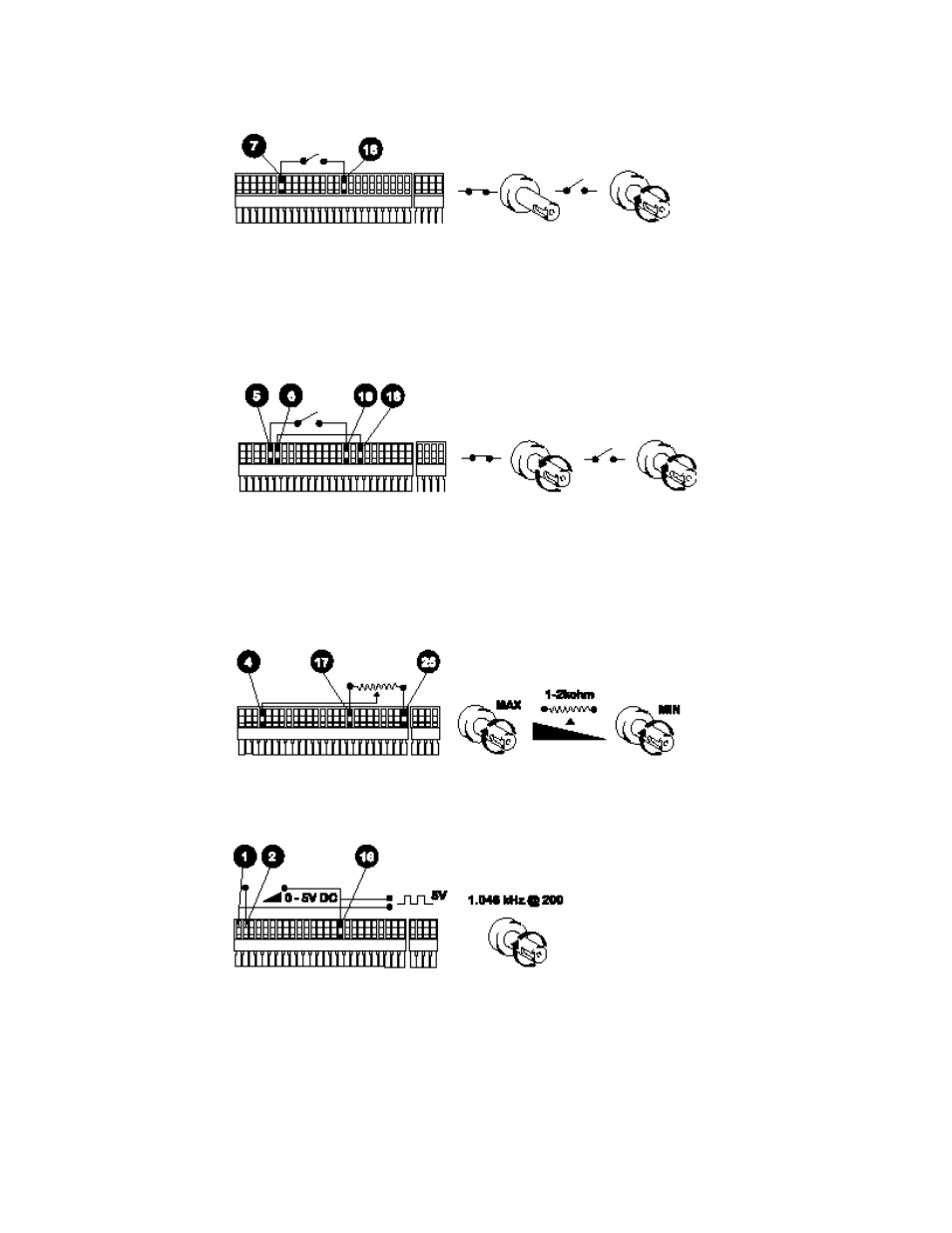
Stop/Start Connect remote switch between pins 7 and 16 of the 25-pin cage clamp
connector. A TTL compatible logic input (Low 0V, High 5V) may be applied to pin 7. Low
input stops the pump, high input runs the pump. With no connection, the pump will default
to running.
Direction Connect remote switch between pins 5 and 16 and disable the front panel
reversing control by linking pins 6 and 18 of the 25 pin cage clamp connector. Open switch
for clockwise rotation, close for counter-clockwise. Alternatively a TTL compatible logic
input (Low 0V, High 5V) may be applied to pin 5. Low input will run the pump in a counter-
clockwise direction, High input in a clockwise rotation. No connection; the pump will default
to clockwise rotation.
Speed A remote potentiometer nominally 1kW and 2kW minimum 0.25W should be wired
as shown. When using a remote potentiometer, do not apply a voltage/current control
input signal at the same time. The pump must be calibrated for 0-12V analogue signal
control under the "PROGRAM" option of Signal in Setup. Alternatively, the potentiometer
may be used for the calibration procedure, instead of using the minimum and maximum
analogue process signal settings, if it is set to its minimum and maximum positions.
Tachometer output This facility can be used to indicate motor speed or total the number
of motor revolutions.
Footswitch A footswitch or handswitch will initiate the dose. The 624Di includes software
protection against spurious signals caused by bouncing of the switch contacts. This feature
is permanently activated (software setting fixed on "other") and only switches without
hardware debouncing should be used.