Remote control – Watson-Marlow 624Di User Manual
Page 8
Watson-Marlow Bredel E-Manuals
http://www.watson-marlow.it/pdfs-global/m-624Di-gb-01.htm[10/07/2012 13:59:15]
Line 1 can be set to change state every time the motor runs, or only when the motor runs
to dispense a dose. The signal can be set high or low when the motor runs. Line 2 changes
state when the pump direction is changed. The screens allow the signal to be set high or
low when the output shaft rotates clockwise.
Pump - When under RS232 control each individual pump must be identified. Select a
number from 1-16.
Max - Sets when the pump can be primed at maximum speed. Standard setting means
Max is enabled during Manual and Setup. Always enabled means the unit can be primed at
any time.
Default - Press Enter at "Yes" to restore factory defaults.
Autostart - If set to On when in Manual mode only, Autostart will allow the pump to
restart pumping automatically after power-up following a mains supply interruption. If set
to Off the pump will restart and return to the Main Menu.
Signal - Step to the desired process signal for analogue control and press Enter. Options
available are 4-20mA, 0-10mA, 0-20mA, 0-5V, 0-10V These signal ranges correspond to
0-200rpm speed control. A confirmation screen will verify settings chosen. If the signal
type required is not shown then use the "program" option to enter in the required signal
levels. The pump is controllable by an analogue process signal of up to 30V or 32mA. The
pump will provide an increasing flow rate for a rising control signal (non-inverted response)
or an increasing flow rate for a falling control signal (inverted response).
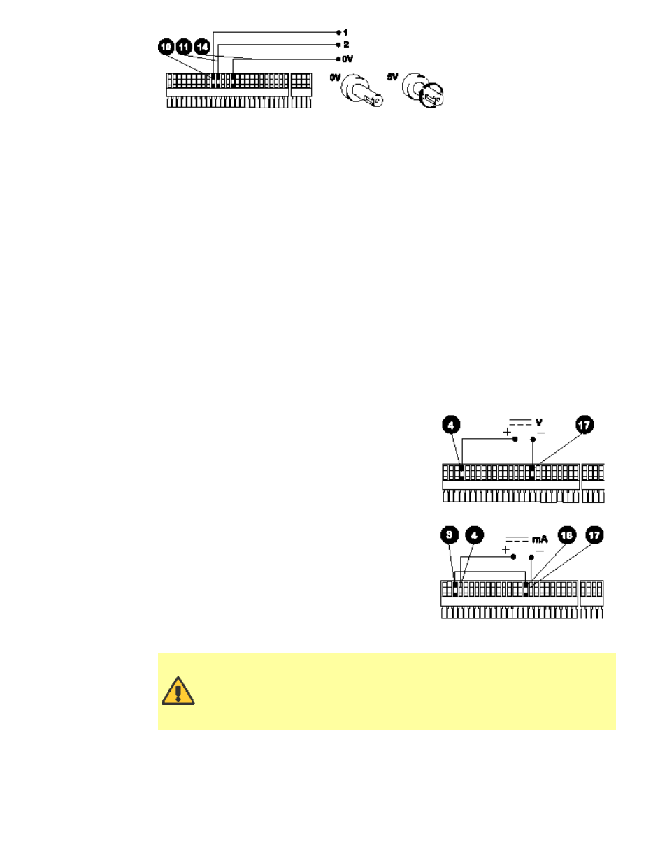
For voltage modes a stable, variable DC voltage
source can be used in conjunction with a DC
voltmeter, (max 30V DC). (Refer to the 25 pin cage
clamp connector wiring detail as an example of
control circuitry) Circuit impedance 100kW. Polarity
set for non-inverted response. Reverse polarity for
inverted response.
For current modes the same DC source can be used
in conjunction with a DC milliampere meter,
(maximum 32mA). (See 25 pin cage clamp connector
detail). Circuit impedance 250W. Polarity set for non-
inverted response. Reverse polarity for inverted
response.
Trim - This function will match the pump's signal
conditioner to the analogue process control signal if
they do not fully coincide. The user will be asked to
apply zero, 20% and the maximum voltage or
current that is required to be the control signal. Press
Enter after adjusting the process signal to each input level.
Never apply mains voltage across pins on the 25-pin cage clamp
connector. Up to 5V TTL may be applied to pins 7 and 5, but do not apply
voltage across any other pins. Failure to heed this warning could cause
permanent damage not covered by warranty. Do not use the mains
power switch to control the pump for a high repetition of stop starts.
The auto-control facility should be used.
Remote control
Pause dose This function will pause a dose for as long as a remote switch remains closed
then allows the dose to continue when the switch is opened. Under Manual mode it will
also act as a remote stop/start. Connect remote switch as in the Stop/Start diagram. Open
to run pump, close to pause or stop pump.