Idcsu components, Idcsu front panel, Idcsu components -3 – Verilink TAC 2130 S/T (880-503296-001) Product Manual User Manual
Page 11: Idcsu front panel -3
Overview
Verilink TAC 2130 User Manual
1-3
•
The TAC 2130-S has the unused bantam jack field and modular
connector removed. It can be used with the same four types of
rear connector modules and supports the same interfaces. The
TAC 2130-S does not support external timing, tail-circuit
timing, or TIU 2850 timing.
•
The TAC 2130-T has the unused bantam jack field and
modular connector removed. It is used only with one of two
special V.35 rear connector modules—the CDM 2035-T and
CDM 2135-T. The TAC 2130-T does not support external
timing, tail-circuit timing, or TIU 2850 timing.
IDCSU Components
The complete IDCSU assembly consists of an application module
and a rear connector module (CDM), together occupying a single
shelf-slot position accessible from the front and back of the
AS2000 shelf. The CDM is installed from the rear of the shelf into
the backplane. The IDCSU module is installed from the front. The
CDM is always installed first and removed last. The IDCSU front
module is installed last and removed first.
IDCSU Front
Panel
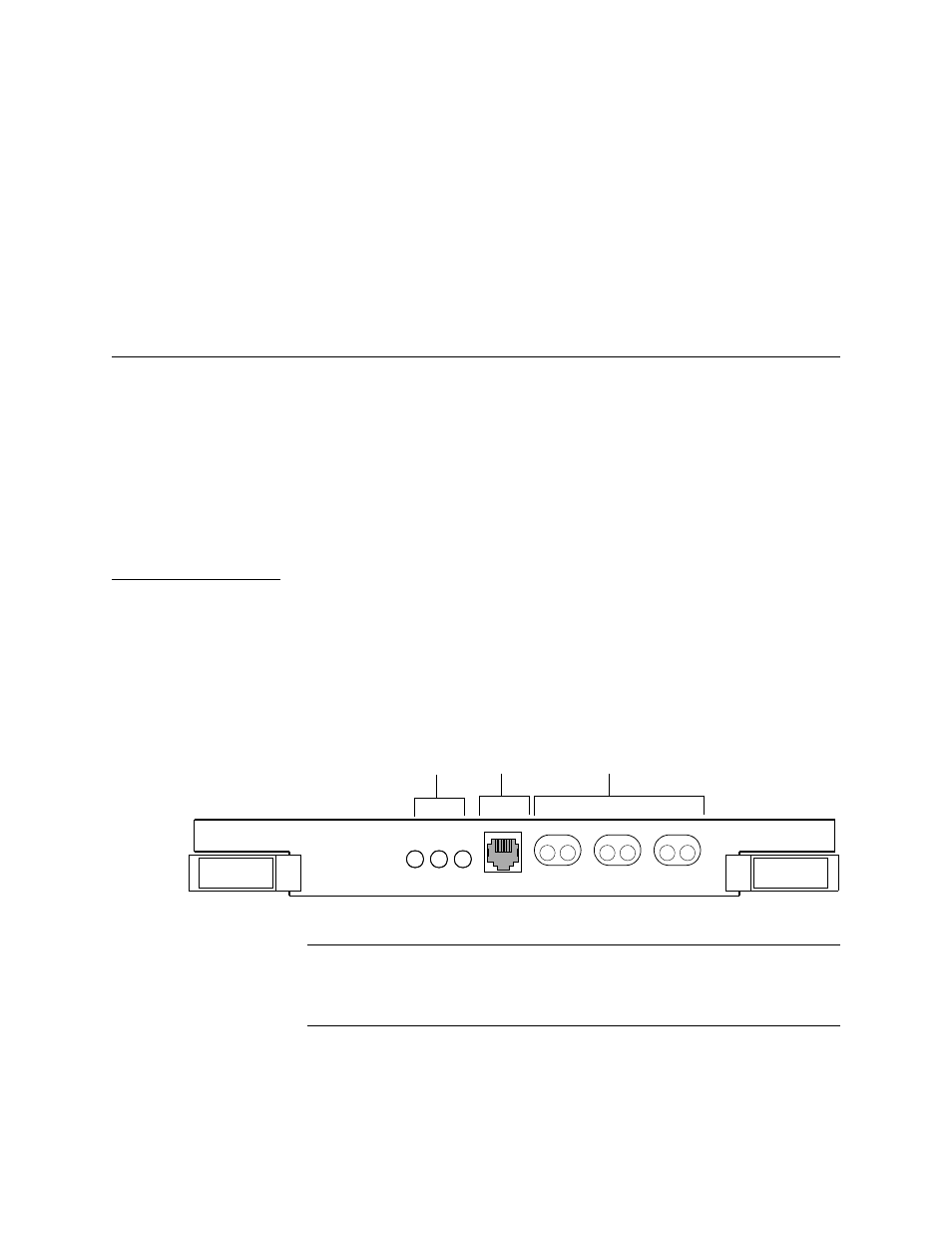
The IDCSU front panel provides LED indicators for visual alarm
indication. It is equipped with dual ejector levers to aid installation
and removal of the module. The following figures
illustrate the
front panel of the three types of IDCSU modules.
Figure 1-1 TAC 2130 Front Panel
NOTE: The bantam-type signal access jacks are present only on the
TAC 2130. They provide access to internal signals within the
module. They do NOT reflect line signals. This jack field
should not be used.
NE
T
EQPT
ST
A
T
EQ
PT
IN
OUT
NET
IN
OUT
MON
IN
OUT
Signal access jacks (not used)
Modular jack
(not used)
Equipment, CSU
Status, an
Network LEDs
2130
TAC