V.54loop, Alarm on dtr loss, Rs-232 option – Verilink PRISM 3030 (34-00208.L) Product Manual User Manual
Page 40: V.54 loop alarm on dtr loss rs-232 option
30
C
HAPTER
3: O
PERATION
V.54 Loop
Selecting Enable allows the unit to respond to in-band V.54 loop commands. If
Disable is selected, the unit ignores these commands.
Alarm on
DTR Loss
Selecting Enable allows the unit to alarm on loss of DTR. The default setting is
Disable.
RS-232
Option
The RS-232 low-speed port option can be ordered as a combination RS-232/232,
RS-232/EIA-530, or RS-232/V.35 application module. The RS-232 port provides a
synchronous DCE interface at subrate speeds for connection to customer DTE. The
data from the port is placed in a single selected DS0 channel of the T1 network
data stream. For switched carrier applications, the RS-232 port provides local RTS
to remote DCD control lead operation at all speeds below 64 kbps.
The RS-232 port provides a bidirectional loop for isolating problems associated
with the interface. Looping the port does not affect data traffic assigned to any of
the other DTE ports. The port loop can be activated from the front panel, the
terminal interface, Telnet across the Ethernet or Token Ring interface, or by the
reception of in-band V.54 loop code. The unit can also be instructed to transmit the
in-band V.54 loop code to loop the corresponding remote end port.
The unit has an internal BERT tester with ten available stress patterns. This
capability can be used by looping one end of the DS0 channel assigned to the
RS-232 port and BERT toward it from the other end. In addition, the BERT can be
activated independently from loops for straight away or point to network testing.
RS-232 BERT is valid only at 56 kbps and 64 kbps toward the DTE.
Figure 3-13 on page 31 is an addition to the DTE Port Configuration menu
diagram. It shows the modified menu options available for the RS-232 port. The
differences are explained in the following paragraphs.
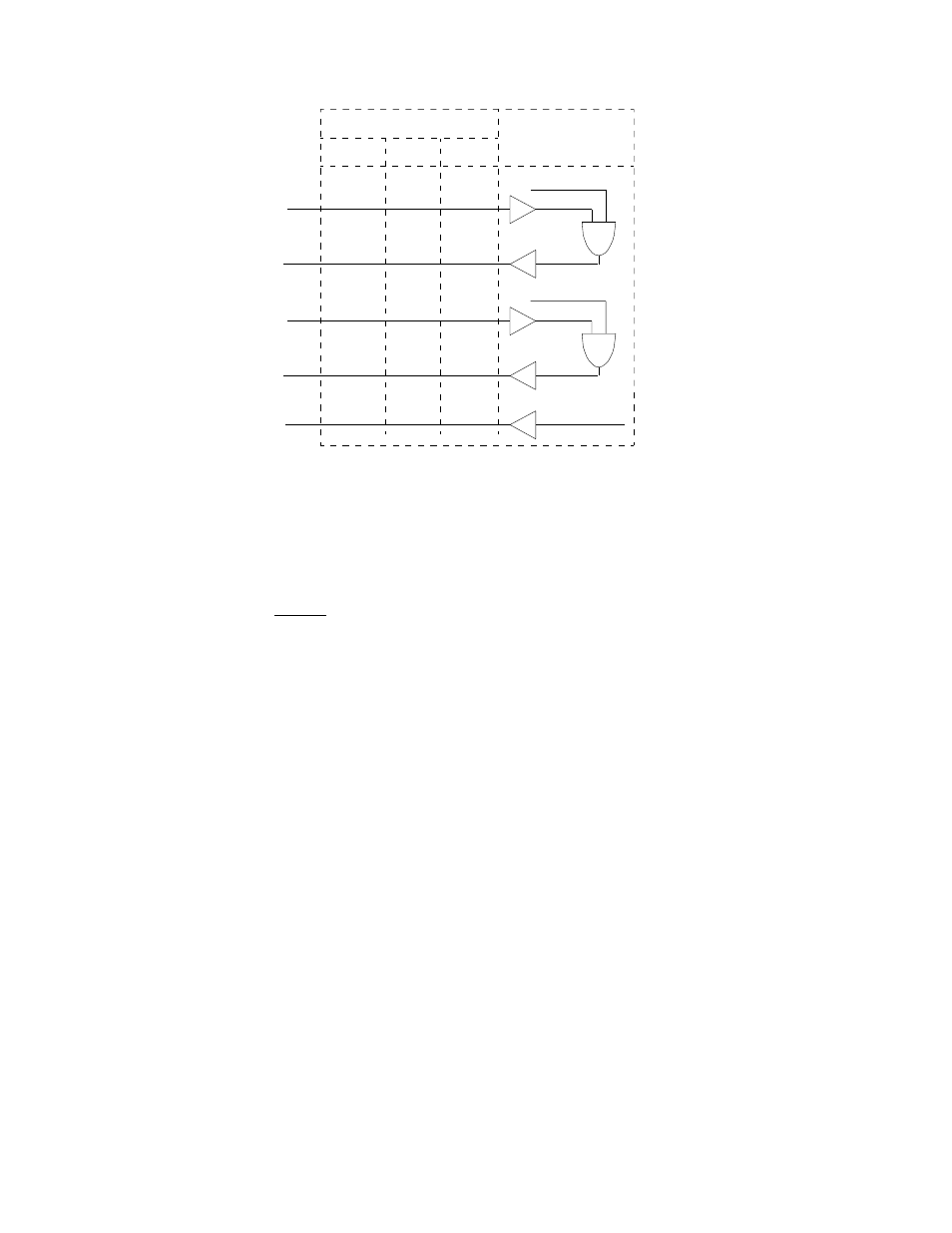
DCD
EIA-530
V.35
RS-449
12/ 30
H
20/23
4/19
5/13
6/22
8/10
F
13/31
E
11/29
D
9/ 27
C
7/25
AND
T1 Receiver In Sync
T1 Loss Of Signal
Connector Pin Numbers
DTR
RTS
CTS
DSR
Alarm State
AND
Port Enabled
PRISM
3030
Figure 3-12 High -Speed Data Port