Verilink PRISM 3021 (34-00262) Product Manual User Manual
Page 32
4-10 Terminal Operation
PRISM 3021
E1-NET
AND
E1-DTE S
TATUS
These two fields display the fault status of the network and
the far-end DTE. They indicate current fault conditions. Sta-
tus indications are described in NET/DTE Status. They do
not indicate that alarm thresholds are exceeded. Status indi-
cations are described in Table 4-D.
N
EAR
L
OOPS
Displays the loop status of the near element.
F
AR
L
OOPS
Displays the loop status of the far element.
Table 4-D Status Indications
Status
Description
-------
No status is available
OK
No errors are currently detected.
ERR
Frame bit errors, CRC errors, or BPVs are detected.
LOS
A loss of signal condition exists.
OOF
An out of frame condition exists.
RAI
Far end is receiving a remote alarm indication signal.
AIS
The far end is receiving an alarm indication signal.
UAS
An unavailable signal state exists due to consecutive
severely errored seconds.
Network Interface
To Network
From Network
RJ-48C
Framer /Deframer
Multiplexer
Receivers /Drivers
Receivers /Drivers
BERT Generator/
Detector
DTE (EIA-530 or V.35)
(100' max.)
Framer /Deframer
DTE (DSX1)
RJ-48C
DSX1, 1' -655'
to cross-connect
From
NET
To
NET
To
NET
From
NET
5
4
2
1
To
Ports
From
Ports
5
4
2
1
1
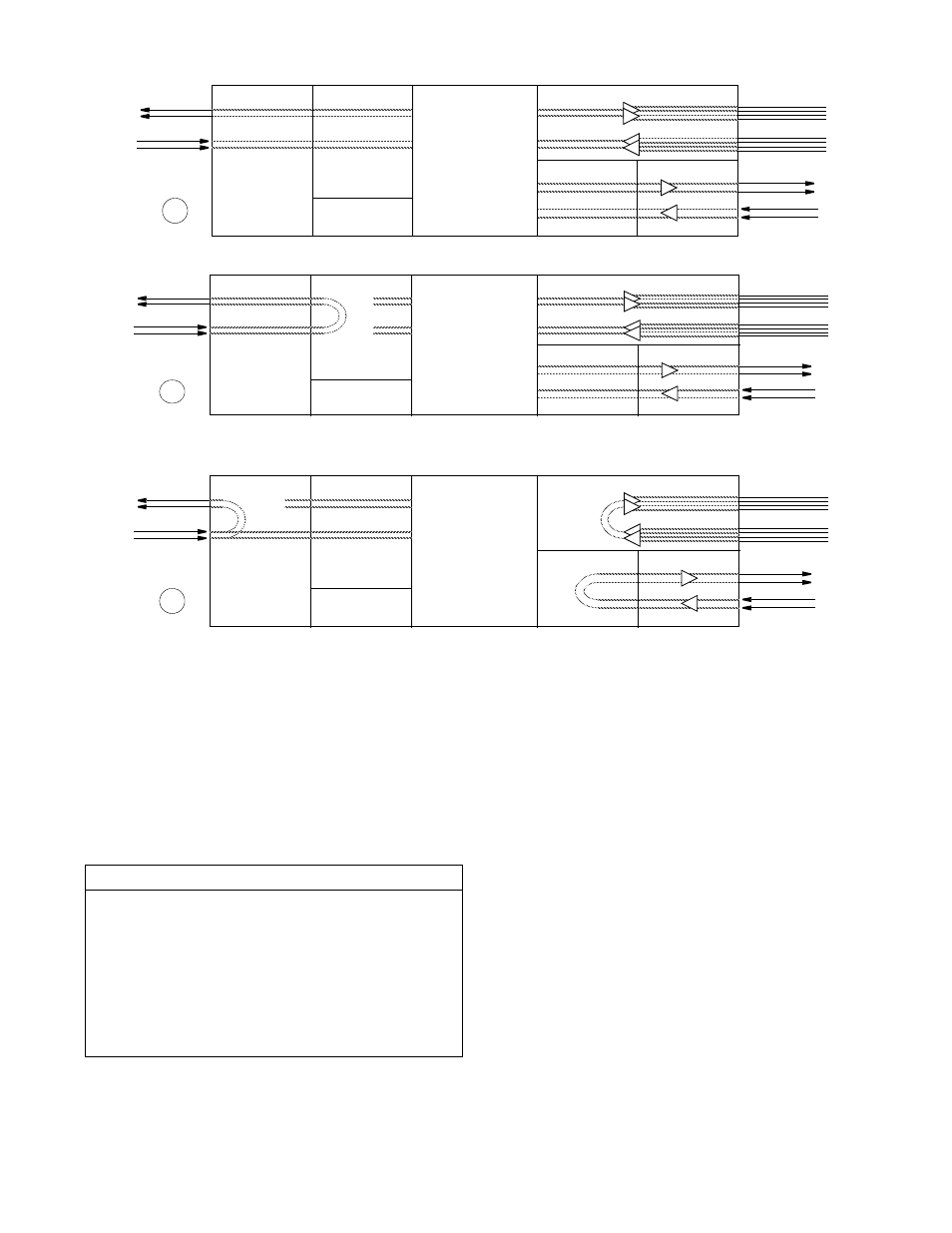
Normal Operation
Network Interface
Framer/ Deframer
Multiplexer
Receivers /Drivers
Receivers /Drivers
BERT Generator /
Detector
EIA-530 or V.35
(100' max.)
Framer /Deframer
DTE (DSX1)
RJ-48C
DSX1, 1' -to 655'
to cross-connect
From
NET
To
NET
To
NET
From
NET
5
4
2
1
To Network
From Network
RJ-48C
5
4
2
1
To
Ports
From
Ports
NET
LLB
3
Network LLB
Network PLB
Network Interface
Framer/ Deframer
Multiplexer
Receivers /Drivers
NET
PLB
Receivers /Drivers
BERT Generator /
Detector
All ones
to DTE
EIA-530 or V.35
(100' max.)
Framer /Deframer
DTE (DSX1)
RJ-48C
DSX1, 1' to 655'
to cross-connect
From
NET
To
NET
To
NET
From
NET
5
4
2
1
To Network
From Network
RJ-48C
5
4
2
1
To
Ports
From
Ports
2
Figure 4-9 Loopback Diagrams