E1-dte option switch s1 -6, Crc4 mode -6, Connections -6 – Verilink PRISM 3021 (34-00262) Product Manual User Manual
Page 14: Supervisory (supv) port -6, Connections, J7 t1 t2, E1-dte option switch s1, Supervisory (supv) port
2-6 Installation
PRISM 3021
source (using TB1, pins 1 and 2). The station timing is con-
figured through the terminal interface. Refer to
Line Parameters on page 4 -13.
Contacts are provided on the rear of the stand-alone unit to
permit connection to an external timing source (using pins 1
and 2). An alternate method for network connection is also
provided with pins 3 through 6. Connection information is
shown in Table 2-S.
E1-DTE Option Switch S1
Switch S1 (Figure 2 -7) is located as shown on Figure 2-5
and is used to configure the E1-DTE parameters listed in the
following paragraphs.
CRC4 M
ODE
Position S1-1 is used to enable or disable CRC4 for the E1-
DTE option as shown in Table 2-O.
E1-DTE L
INE
C
ODE
Position S1-2 selects the E1-DTE line code as shown in
Table 2-P.
S
PARES
Positions S1-3 through S1-7 are not used and should be left
Down.
E1-DTE T
ERMINATION
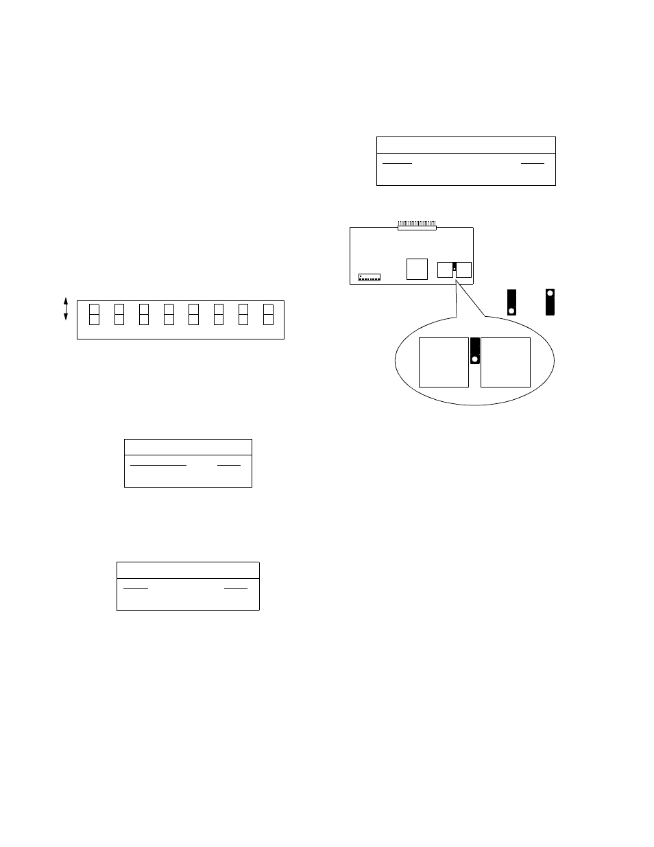
Position S1-8 is used to select the E1-DTE termination as
shown in Table 2-Q. This setting must agree with the place-
ment of the J7 shown in Figure 2-8.
Connections
Supervisory (SUPV) Port
The front panel supervisory (SUPV) port serves several
functions. The unit firmware may be accessed through this
port (see Terminal Interface on page 4 -1) as well as the Call
On Alarm feature (see Management Ports on page 4 -18).
This port may be accessed through either a direct connec-
tion or a dial-up connection using an AT-command-set-com-
patible modem. The modem should be optioned to ignore
DTR, enable auto answer, inhibit command echo, and return
verbose result codes.
If the unit is called and sent a break command
before receiving the connect message, the modem
hangs up.
The 8100A Site Manager may be directly connected to the
eight-pin modular serial port connector labeled SUPV (refer
to SUPV Port Rate on page 2-3). When a group of elements
is connected in an NMS chain, the 8100A site Controller
may be connected to the supervisory port of any one of the
elements. This element can then route messages onto the
NMS chain to reach the other elements. The COA feature
only works through the supervisory port.
Table 2-O CRC4
CRC4
S1-1
CRC4 enabled
Down
CRC4 disabled
Up
Table 2-P E1-DTE Line Code
E1-DTE Line Code
S1-2
HBD3
Down
AMI
Up
7
6
5
4
3
2
1
Do
wn
Up
8
CRC4
E1
-D
T
E
Sp
ar
e
Sp
ar
e
Li
n
e
Mo
de
T
erm
in
atio
n
Sp
ar
e
Sp
ar
e
Sp
ar
e
Figure 2-7 Switch S1
L
ine
C
o
de
Table 2-Q E1-DTE Termination
E1-DTE Termination
S1-8
75 ohm
Down
120 ohm
Up
Figure 2 -8 Setting J7 on the E1-DTE Option Card
S1
J7
T1
T2
75 ohm 120 ohm
J7
T1
T2
E1-DTE Option Card