Standalone connections -7, Dte port -7, 1051 chassis connections -7 – Verilink PRISM 3021 (34-00262) Product Manual User Manual
Page 15: Dte interfaces -7, Table 2-s, Standalone connections, 1051 chassis connections
Installation 2-7
PRISM 3021
This port is a DCE port configured for 8 bits, no parity, and
1 stop bit. The physical connections are 8-pin modular jacks
(electrically RS-232). Refer to TxPORT Customer Service
on page 1-4 for cable information. The pinout for this port
is shown in Table 2-R.
Standalone Connections
The standalone version of the 3021 has the same connec-
tions as the 1051 nest-mount chassis, except that there is no
34-pin Winchester-type high-speed DTE connector. Any
information unique to the standalone rear panel is in this
section, otherwise follow the reference in Table 2-S. Pinouts
for the standalone rear panel connections are provided in
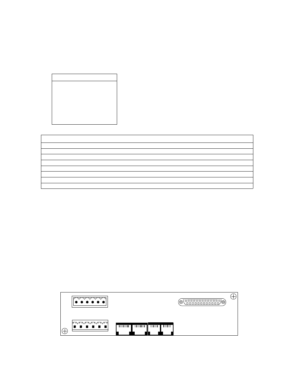
Table 2-S. Figure 2-9 shows the rear panel of the standal-
one chassis.
DTE PORT
The DTE port pinout is shown in the column labeled DB-25
25-pin of Table 2-T.
1051 Chassis Connections
The 1051 nest-mount chassis provides all the necessary con-
nections to in Figure 2-13 and Figure 2 -14 on page 2-11.
DTE I
NTERFACES
Both models of the TxPORT 1051 chassis provide connec-
tion to the customer equipment. Each slot of the 1051-2 has
a corresponding E1 DTE 8-pin RJ-48 connector and a high-
speed DTE female 25-pin connector located on the chassis
rear panel. The 1051-3 chassis is similar except that it has a
high-speed DTE 34-pin connector instead of the 25-pin con-
nector. The pinout for the E1 DTE RJ-48 connector is given
in Table 2 -V and the pinout for the high-speed DTE con-
nectors is given in Table 2 -T.
Table 2-R Supervisory (SUPV) Port Connector
Pinout
Pin
Supervisory Port Interface
1
Control Out
2
Signal Ground
3
Data Out
4
Data In
5
Signal Ground
6
Control In
6
1
Figure 2-9 Rear Panel of 3021 Standalone Chassis
6
NM
S IN
1
6
NM
S OUT
1
8
E1
DTE
1
8
NET
W
O
R
K
1
ALARM /POWER
NETWORK/EXT CLK
DT
E
PO
R
T
1
13
14
25
1
6
Table 2-S Pinouts for Standalone Rear Panel Connectors
Pin
NMS IN
NMS OUT
E1 DTE
NETWORK
POWER
EXT CLK
1
Not Used
Not Used
Tip Output
Data In
48 V Return
Network Input (Tip)
2
Signal Ground
Signal Ground Ring Output
Data In
Signal Ground
Network Input (Ring)
3
Data Out
Data Out
Not Used
Not Used
-48 VDC
Network Output (Tip)
4
Data In
Not Used
Tip Input
Data Out
Frame Ground
Network Output (Ring)
5
Signal Ground
Signal Ground Ring Input
Data Out
Alarm Contact
Station Clock (Ring)
6
Not Used
Not Used
Not Used
Not Used
Alarm Common Station Clock (Tip)
7, 8
Chassis Ground
Chassis Ground