Verilink DIU 2130 (880-503297-001) Product Manual User Manual
Page 96

DIU/DIM Details
7-16
Verilink
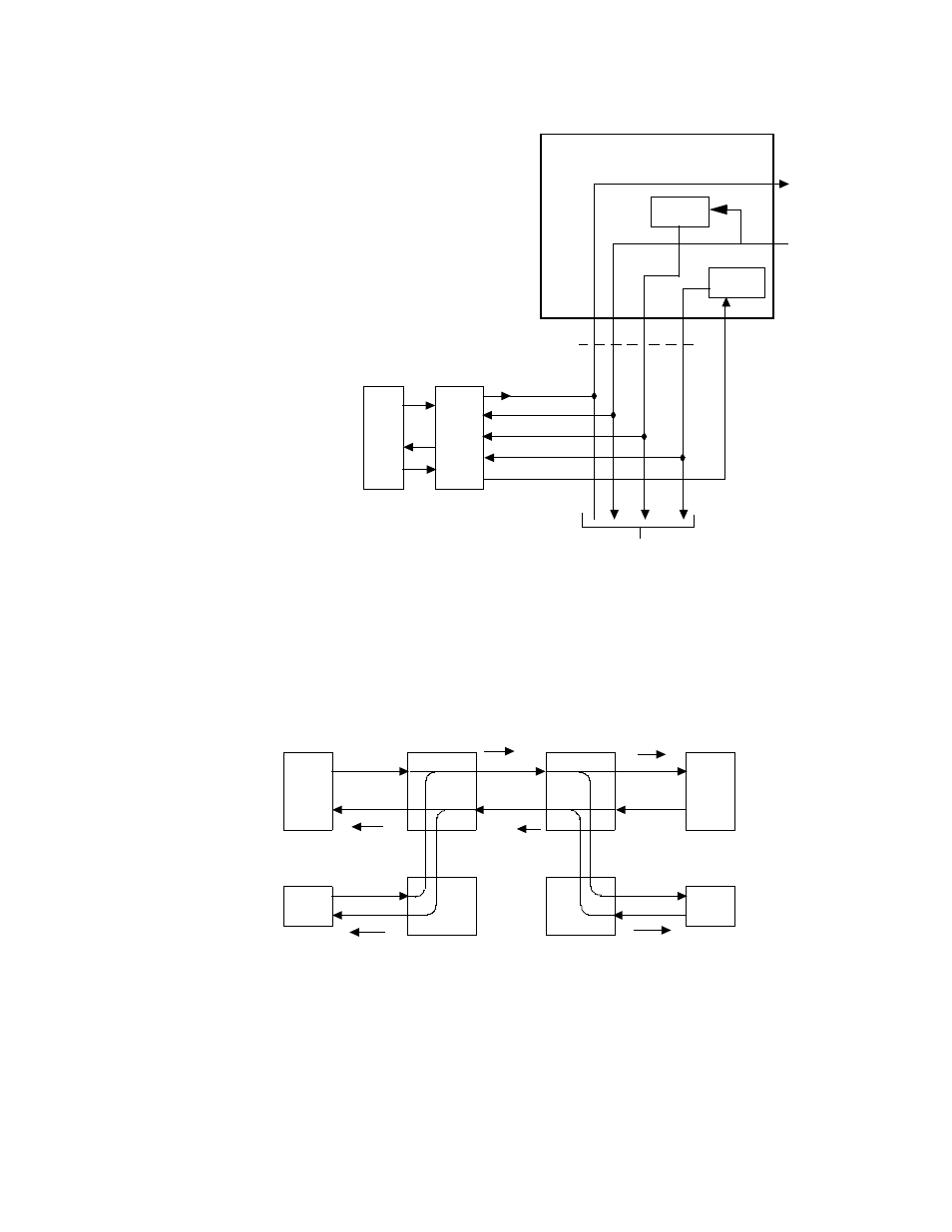
Figure 7-18 Data Equipment Timing (T1 Multiplexer Mode)
Figure 7-19 shows alarm processing when LOF is detected from the
network and CSU drop-and-insert is toward the network. The LOF-
detecting CSU sends all-ones on channels 1 through 12 toward the
DS1 channel bank for channel conditioning.
Figure 7-19 Drop-and-Insert LOF/RAI Processing (Detection from the Network)
NCC OR TAC
DATA BUS A OR B
TO/FROM
NETWORK
DATA
BUS C
XMT DATA
RCV DATA
DIU
2130
DATA
EQ
RCV CLOCK
XMT CLOCK
TRANSMIT
TT
XMT TIMING (TT)
TO/FROM OTHER DIUs
CLOCK
RECEIVE
CLOCK
DS-1
CHAN
BANK
DATA
EQPT
INSERT
DROP
CSU
NETWORK
DIUs
Channel conditioning (negate CTS, DSR
and DCD; send ALL ONEs to data
equipment) (Note 2)
EQPT VF (ch. 1 - 12) +
Insert DIU data (ch. 13 -
24) + RAI
ALL ONEs (ch.
1 - 12)
(LOF)
CSU
DS-1
CHAN
BANK
DIUs
DATA
EQPT
INSERT
DROP
Channel conditioning (negate CTS and DSR,;
send ALL ONEs to data equipment)
(Note 2)
VF (ch. 1 - 12) +
ALL ONEs (ch.
13 - 24)
EQPT VF +
Insert DIU
data
(RAI)
(VF on
ch. 1 - 12)
(VF on
ch. 1 - 12)
(ch. 13 - 24)
(ch. 13 - 24)
NOTES:
1. In the SF mode, the CSU neither generates nor responds to a received Yellow Alarm. Therefore,
far-end channel conditioning does not occur with SF framing.
Drop and insert towrd Network
